Fixing Modern Replacement Cords on Singer Bakelite Controllers
A Note on Controller Compatibility
While this article specifically highlights the classic Singer Bakelite button foot controller, this issue isn’t limited to a single model. Many early metal Singer controllers, as well as later Bakelite and molded plastic vintage models, utilize the exact same thread-riser design on their terminal blocks. If you are working with a modern replacement cord on almost any vintage 3-pole Singer foot control, you will likely encounter these same terminal gap and lead routing hazards.

Issue 1: Forked Terminal Ends
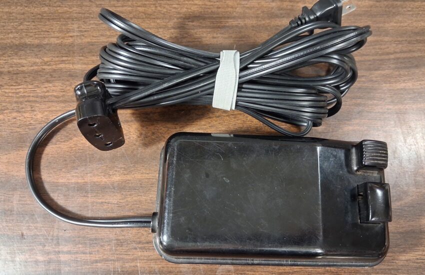
Over the years, I’ve noticed a recurring issue that deserves more attention: modern replacement cords for Singer 3-pole plugs and Bakelite button foot controllers come with forked terminal ends. These terminals are too thin for the motor controller’s clamping screws to secure properly unless you add a washer to bridge the gap created by the thread riser.

Understanding the Terminal Gap Issue
Modern replacement cords use flat, stamped fork terminals, whereas original Singer cords used thicker, rolled eyelet terminals. Because modern forks lack the height of the original eyelets, installing them without modification creates a subtle but dangerous electrical issue:
- Left Panel: Without a spacer, flat modern fork terminals remain loose because the clamping screw bottoms out against the riser before it can compress the thin metal. This loose connection leads to high resistance, heat buildup, and intermittent power loss.
- Middle Panel: The factory thread riser was engineered to accommodate the depth of Singer’s original rolled eyelet terminals while adding extra thread engagement for the screw. However, its raised lip creates an offset gap that modern flat terminals cannot bridge on their own.
- Right Panel: Adding a small washer between the screw head and the fork terminal fills the excess space. This restores the proper clamping thickness, allowing the screw to secure the terminal tightly against the bracket for a safe, low-resistance connection.
Solution One: Fill the Gap with a Washer (Recommended)

A #6 SAE washer is the simplest way to bridge the gap. Select a washer with an inner hole wide enough to clear the raised thread riser—variations in washer packs mean some might bind. Together, the washer and fork terminal must be thick enough that the screw compresses them fully before bottoming out. When tightened down, the connection should be rock-solid with no play or movement.
Solution Two: Making Custom Eyelets Using Eyelet Pliers
For a clean, permanent fix without extra washers, strip the leads on your replacement cord and crimp fresh brass eyelets using standard eyelet pliers. While Singer originally used a proprietary mechanical bind with light plating, this method reproduces the exact depth and footprint of their vintage rolled ringlets. It’s the ideal route if you prefer a period-correct restoration, though it takes more time and is slightly less mechanically robust than clamping a forked terminal under a solid washer.

How to Crimp Custom Wire Eyelets:
It’s a good idea to practice this using scrap wire a few times before working on your new controller cords.
- Trim and Stagger Leads: Test-fit the wire in your controller. Trim the shorter lead so it lands directly on its terminal, and leave the outer lead long enough to sweep cleanly around the ceramic core mounting screw.
- Strip and Wrap Copper: Strip back enough insulation to wrap the wire around the brass eyelet barrel twice. Twist the bare strands tightly together, then wrap the wire cleanly around the barrel.
- Crimp with Eyelet Pliers: Insert the assembly into your eyelet pliers and apply firm pressure to flare the eyelet rim down securely over the copper strands.
Important Safety Note on Soldering:
Avoid soldering the stranded wire prior to clamping it under the terminal screw. Solder deforms under screw pressure over time (cold flow), which can cause the terminal screw to back off, resulting in a loose connection, high resistance, and excessive heat. A firm, mechanical crimp using eyelet pliers is all that is needed for a reliable, low-resistance connection.
Modern DIY Eyelet vs. Original Singer Ringlet

Proper Clearance on the Terminal Riser
Once crimped, the custom eyelet rests completely flat over the factory thread extension, restoring the necessary material thickness so the clamping screw secures the lead tightly.


Bonus Tip: Missing the Right-Sized Washer?
While adding a small washer is the quickest alternative if you aren’t crimping new eyelets, there’s a great option if you don’t have the right washer size on hand: clip the original rolled eyelet terminals off the old Singer cord. You can slip these old eyelets directly onto the clamping screws above the new fork terminals to serve as custom, perfectly sized factory spacers.

Issue 2: Equal-Length Terminal Leads
While secondary to the terminal gap issue, another common problem with modern replacement cords is that they are manufactured with equal-length terminal leads. Depending on how the cord exits your foot controller, one lead typically needs to be shorter than the other to cleanly clear the internal mounting screws securing the ceramic core to the base.

Managing Lead Clearance and Wire Routing
Because of how the wiring routes to the terminals, one leg inherently has to travel a longer path around the internal mounting screw than the other. When a modern cord comes with equal-length leads, the leg that needs to go around the screw ends up too short to take the long way, forcing it straight across the screw head:
- Left Panel (Forced Straight Path): When both leads are equal length, there isn’t enough slack on the outer leg to route it safely around the mounting screw. As a result, the wire gets pulled directly across the screw head. When you fasten the Bakelite cover back on, it pinches the wire against the screw, crushing the insulation and creating a serious short-circuit hazard.
- Right Panel (Proper Clearance): Staggering the lead lengths—or trimming the inner lead while leaving the outer lead long enough—provides the necessary slack to sweep the wire cleanly around the mounting screw and along the outer perimeter, keeping it completely safe from being pinched.
Pro Tip: Working with Pre-Terminated Cords
If you are installing a pre-made replacement cord with factory-crimped terminals and don’t have the tools to cut, strip, and attach new terminals, you can still use the cord as-is. Just take extra time during assembly to carefully direct the wire away from all mounting points before tightening down the controller housing.
- Disclaimer:
- The provided information is for general guidance only and shouldn’t be taken as professional advice.
- Safety Warnings:
- Electrical work is dangerous and should only be performed by trained and experienced professionals.
- Do not attempt to work on electrical appliances unless you have the necessary knowledge and expertise.
- Improper electrical work can result in injury, death, and property damage.
- Follow local electrical codes, and consult a qualified electrician for guidance.
- Information Accuracy:
- Any information provided here is for general and informational purposes only and so, should not be construed professional advice.
- We make no warranties or representations of any kind, express or implied, regarding the accuracy, adequacy, validity, reliability, or completeness of this information.
- You are solely responsible for verifying the accuracy of the information and for any actions taken based on it.
- Liability:
- We accept no liability for loss or damage of any kind, including but not limited to direct, indirect, incidental, consequential, or special damages, in connection with the use of this information.
- You’re responsible for ensuring that work performed based on this information complies with all safety standards.