Singer 15 series tensioner – early to mid 1930’s

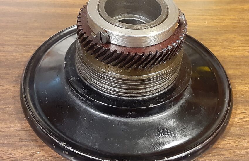
The tensioner above is from a 1935 Singer 15-91, and I have one from 1932 with the same style tension unit. This article is for the tensioner that looks like the one above since the ones that preceded it and all that followed it are quite different. They may have similar parts, and some parts may be interchangeable, but sometimes they are installed in a different order or the size or shape may have changed between designs.
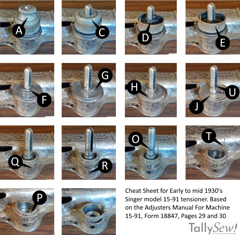
Parts view with names
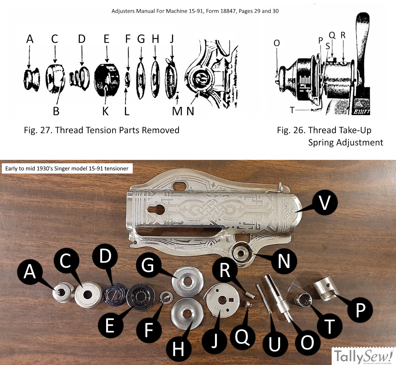
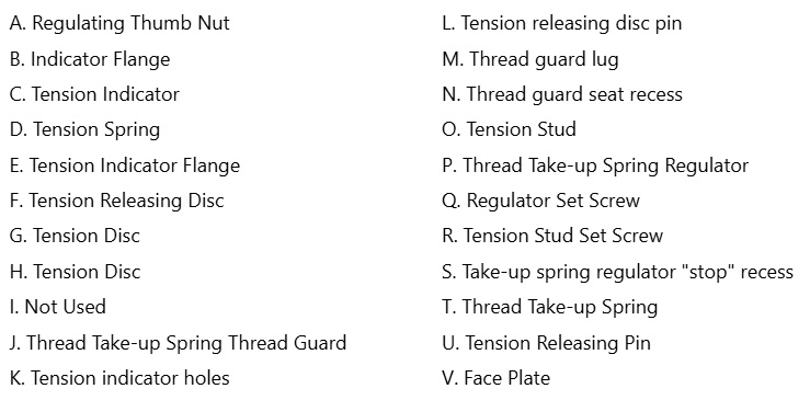
A. Regulating Thumb Nut
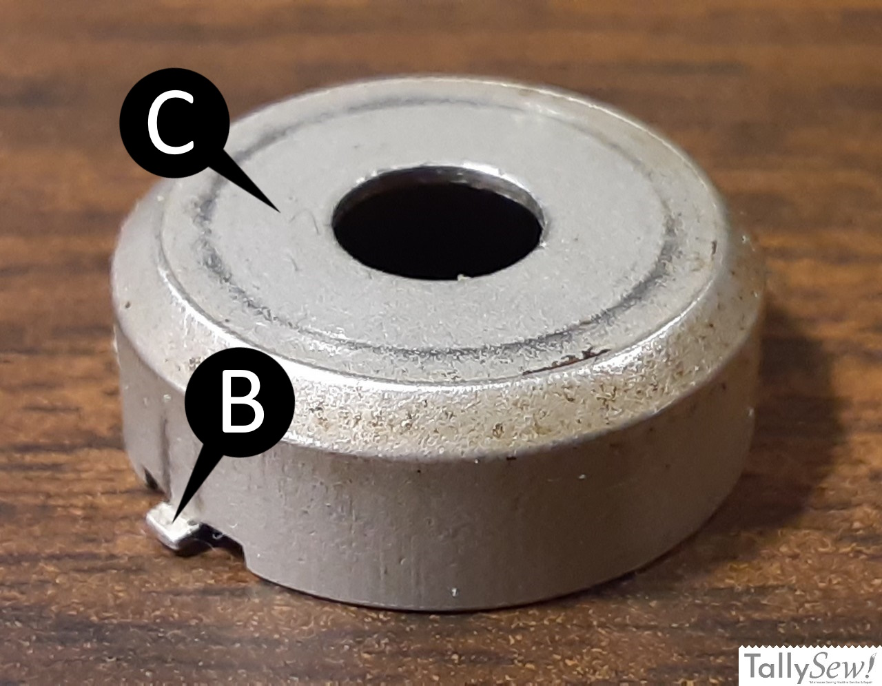
B. Indicator Flange
C. Tension Indicator
D. Tension Spring
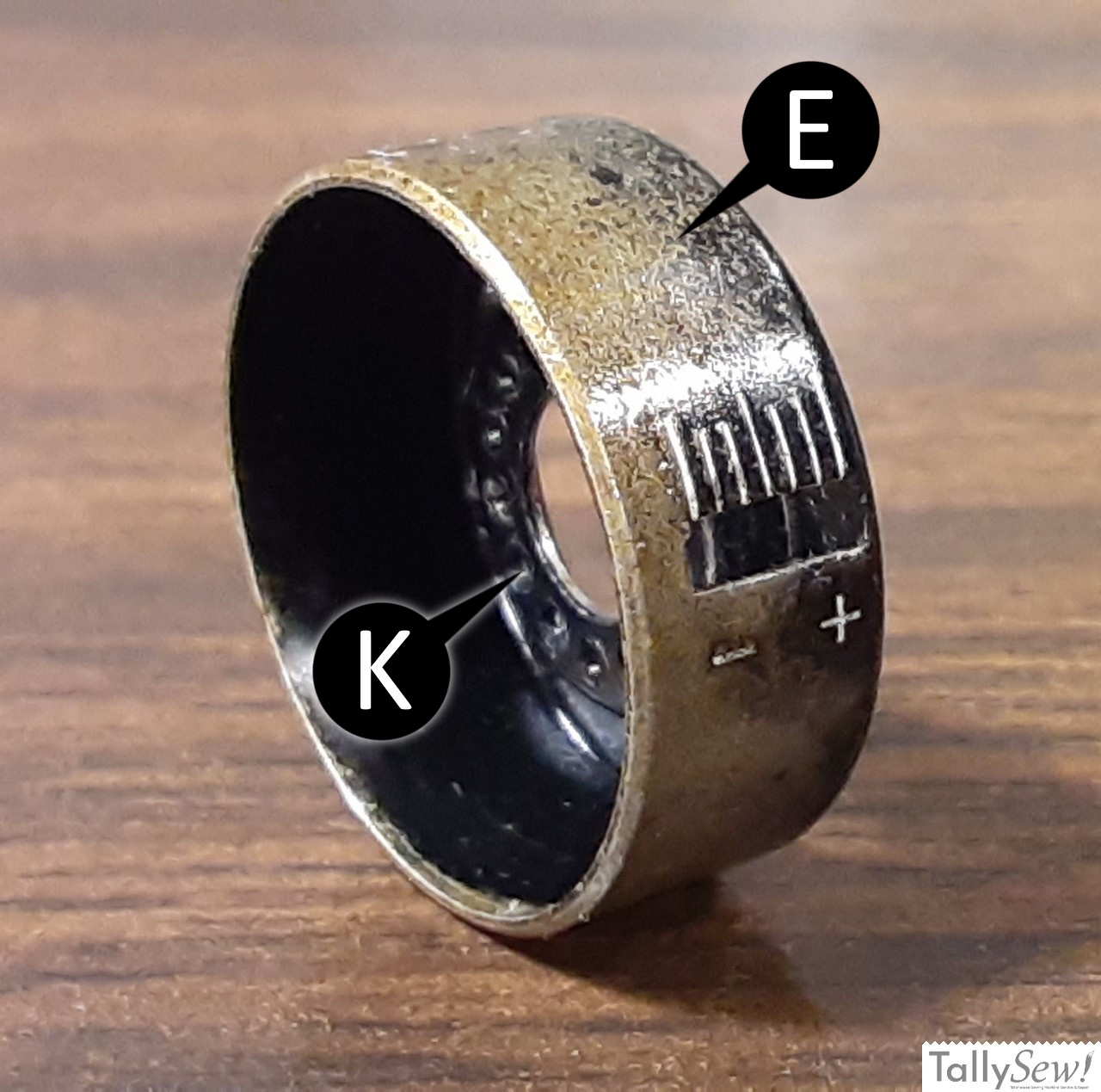
E. Tension Indicator Flange
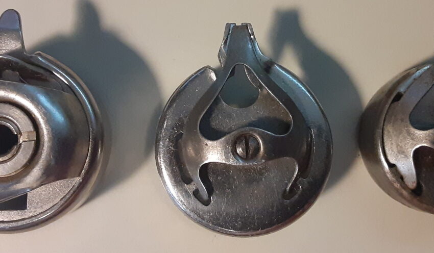
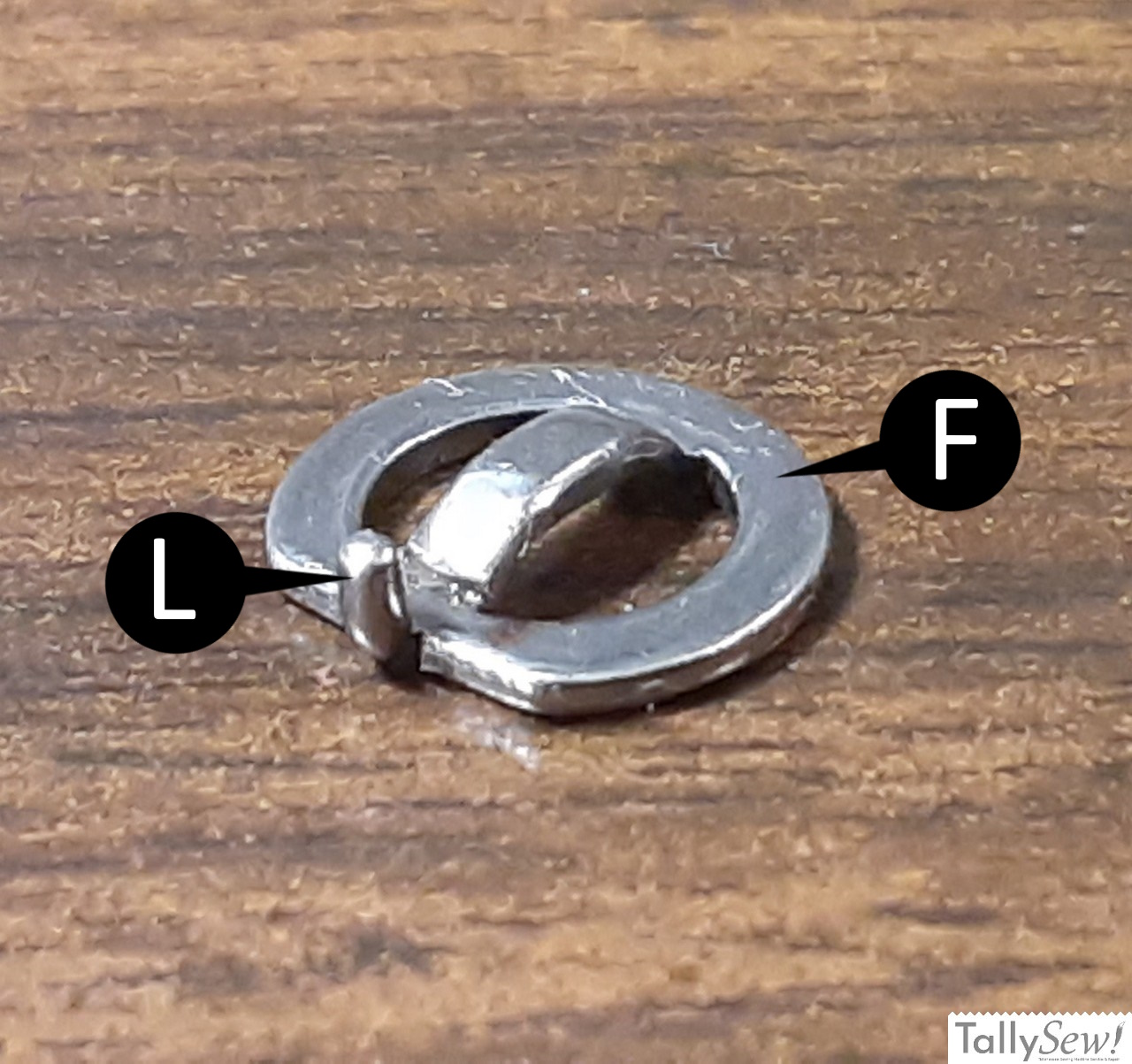
F. Tension Releasing Disc
G. Tension Disc
H. Tension Disc
I. Not Used
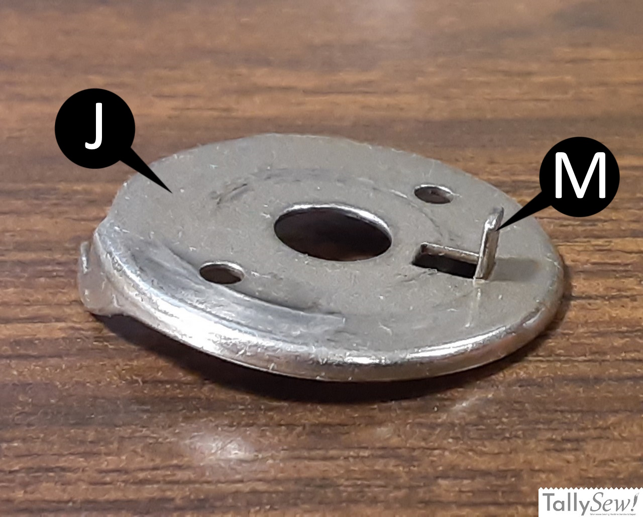
J. Thread Take-up Spring Thread Guard
K. Tension indicator holes
L. Tension releasing disc pin
M. Thread guard lug
N. Thread guard seat recess
O. Tension Stud
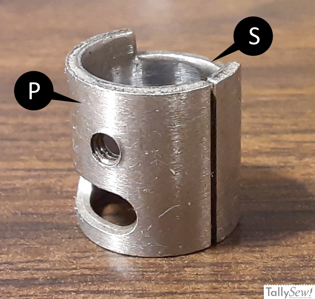
P. Thread Take-up Spring Regulator
Q. Regulator Set Screw
R. Tension Stud Set Screw
S. Take-up spring regulator “stop” recess
T. Thread Take-up Spring
U. Tension Releasing Pin
V. Face Plate
To adjust the tension and regulate the action of the thread take-up spring.
The tension of the thread take-up spring (T, Fig. 26) should be just enough to take up the slack of the needle thread until the eye of the needle reaches the goods in its descent. Loosen set screw (R, Fig. 26) and turn the tension stud (O, Fig. 26) to the right to increase the tension of the thread take-up spring (T) or to the left to decrease the tension of the spring. When the correct tension is obtained, tighten the set screw (R).
The height of action of thread take up spring (R) is determined by the position of the recess (S) on the outer end of the thread take-up spring regulator (P). The upper end of this recess (S) acts as a “stop” for spring (T) at the desired height of spring action. If adjustment is required, loosen screw (Q) and turn the thread take-up spring regulator (P) to the right to lessen the height of the spring action, or to the left to increase the height of spring action. When desired height of a spring action is obtained, tighten screw (Q).
To remove and replace thread tension parts.
Thread tension Parts can be removed in the following order, as shown in figure 27: thumb nut (A), tension indicator (C), tension spring (D), tension indicator flange (E), tension releasing disc (F), tension discs (G and H), thread take-up spring thread guard (J). Replace the parts by reversing the foregoing order of their removal, with the lug (M) of the thread guard (J) and the narrow recess (N) at the underside of the thread guard seat. Have the pin (L) of the tension releasing disc (F) pointing away from the face plate so that it will engage one of the holes (K) in the tension indicator flange (E), with the indicator flange in the most readable position and with the projection (B) of indicator (C) in the graduated slot of the indicator flange (E).
~ Singer Adjusters Manual For Machine 15-91, Form 18847, Pages 29 and 30
Cheat Sheet / Step by step disassembly