Singer 15 series needle bar box
The Singer model 15 series machines is simple and robust. I’m going to give you an overview of how to assemble the needle, and presser foot bar, the presser foot lift and take-up arm, mostly using my 1932 Singer 15-91 as an example. If you need to know how to disassemble the needle bar box then start at the end of the article and work your way to the beginning.
Since this overview turned out much longer than I expected, I’ll just cover how to install the parts into the machine here. I’ll be adding more articles covering how to make adjustments to those parts.
Installing the needle bar
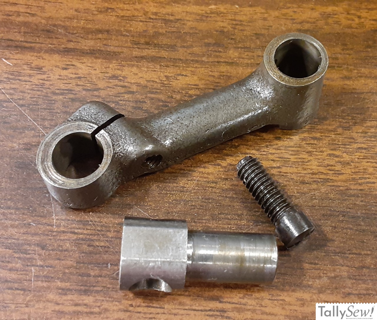
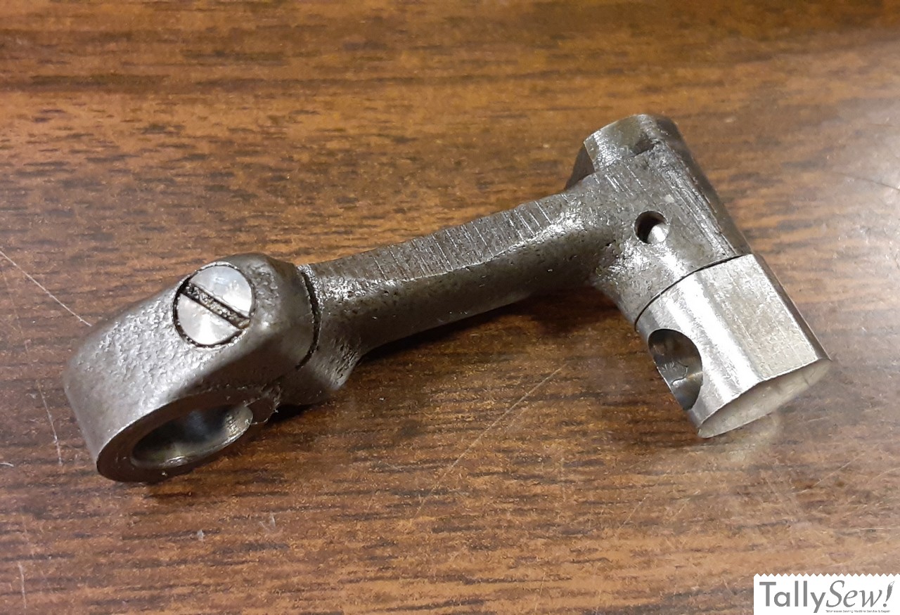
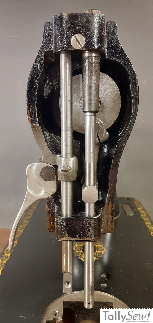
The Needle bar connecting link, stud, and set screw assembly simply slides onto the connecting link post. The head of the connecting link clamping screw at the top of the connecting link will be pointing to the right, and the needle bar connecting stud with the hole for the needle bar will be at the bottom and pointing out.
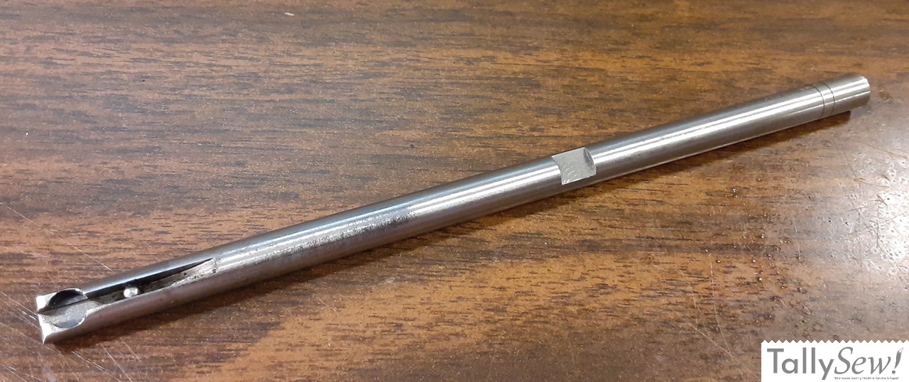
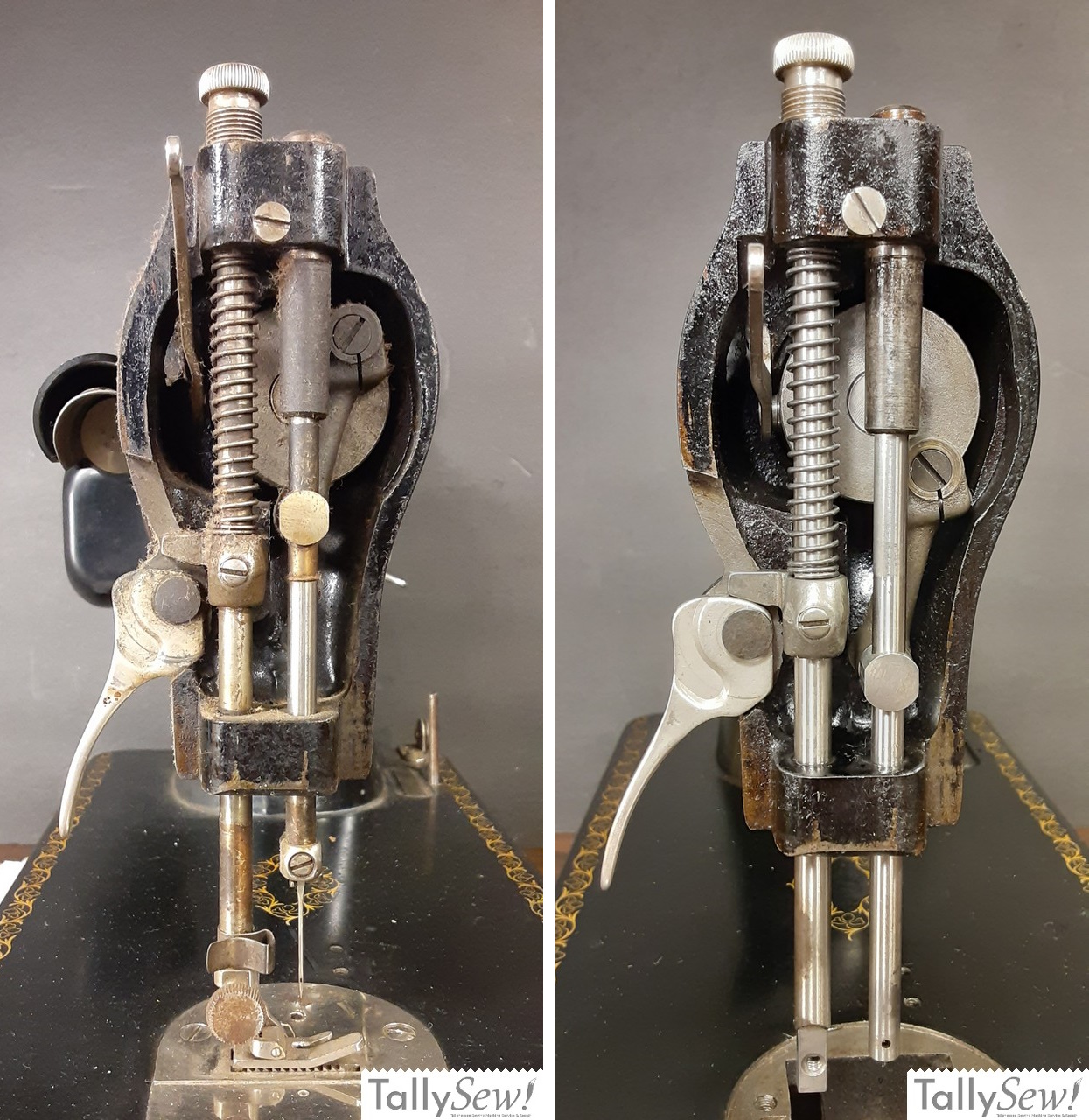
The needle bar has a flat milled into it just a little above the middle of the shaft. That flat will face towards the handwheel end of the machine and the needle bar connecting stud set screw will clamp onto the needle bar on that flat area.
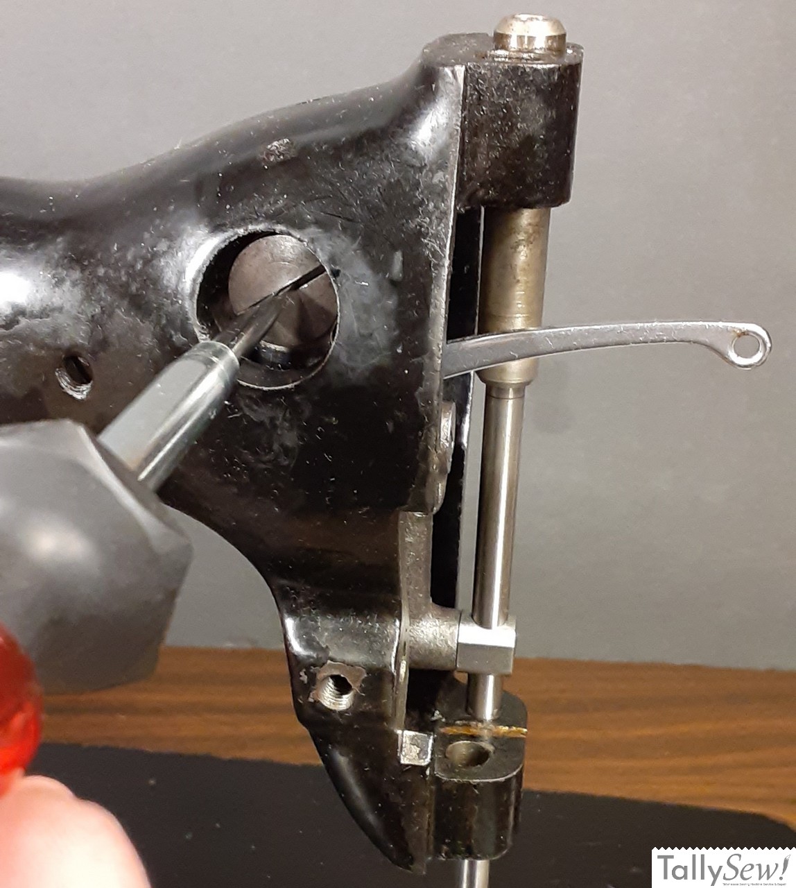
Making sure the Needle bar connecting link is at it’s lowest point, slide the needle bar in from the top until the flat is even with the needle bar connecting stud set screw. Then from the handwheel side of the needle bar box, use a flat blade screwdriver through the hole and gently tighten the needle bar connecting stud set screw. Don’t bother making it too tight since you’ll need to adjust the needle bar height later on.
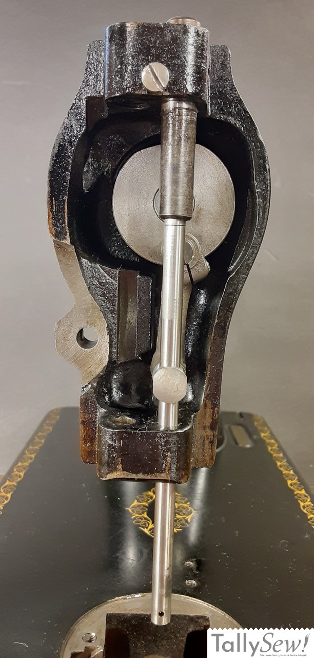
Installing the presser bar lifter
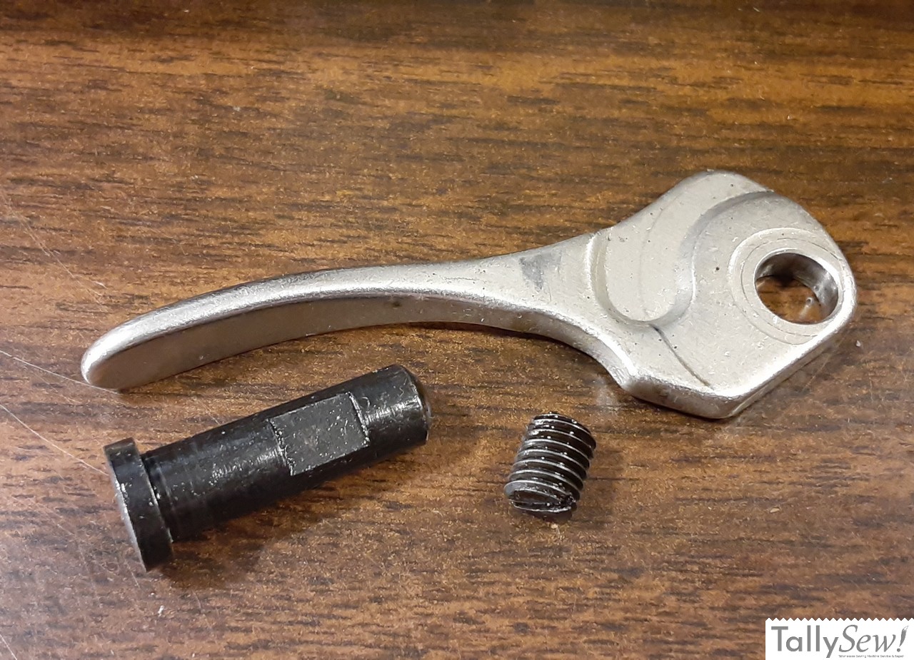
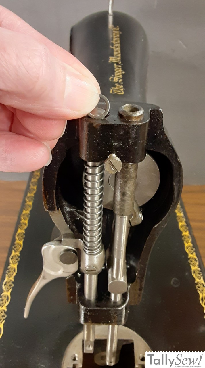
Presser bar lifter, Presser bar lifter hinge stud, Presser bar lifter hinge stud set screw
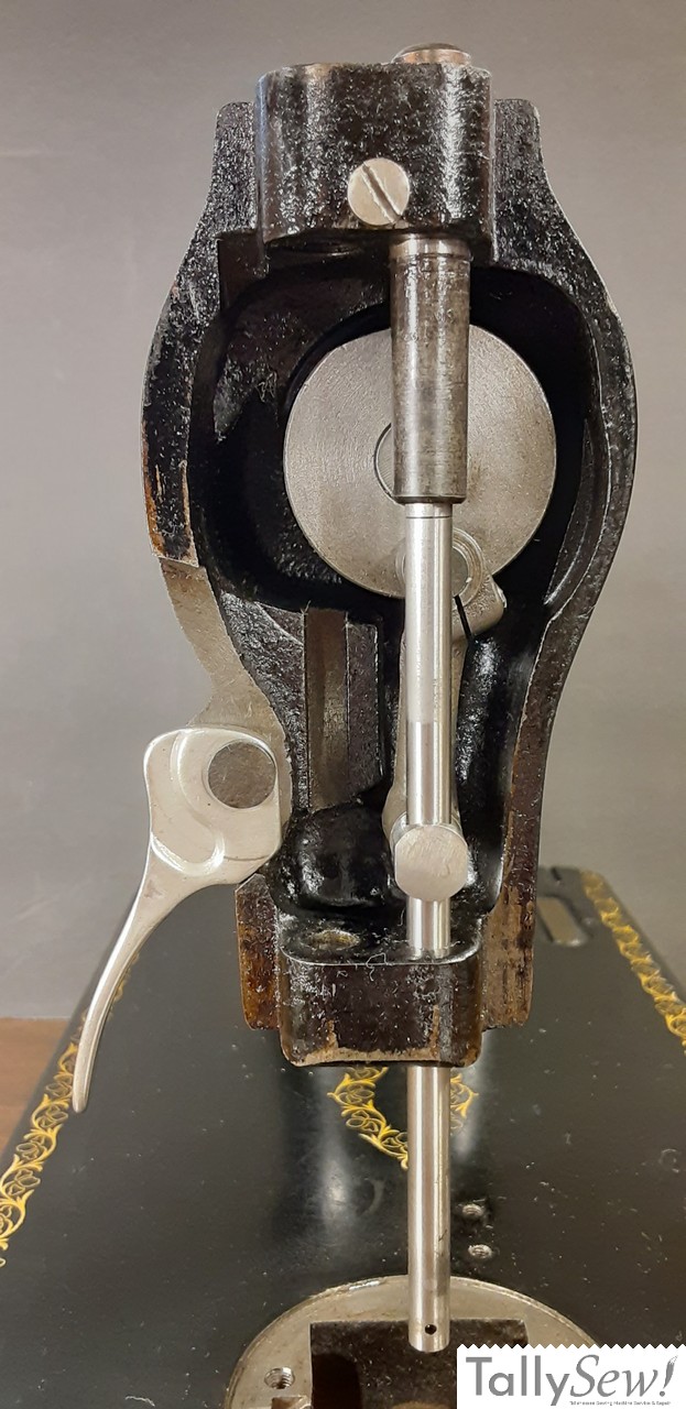
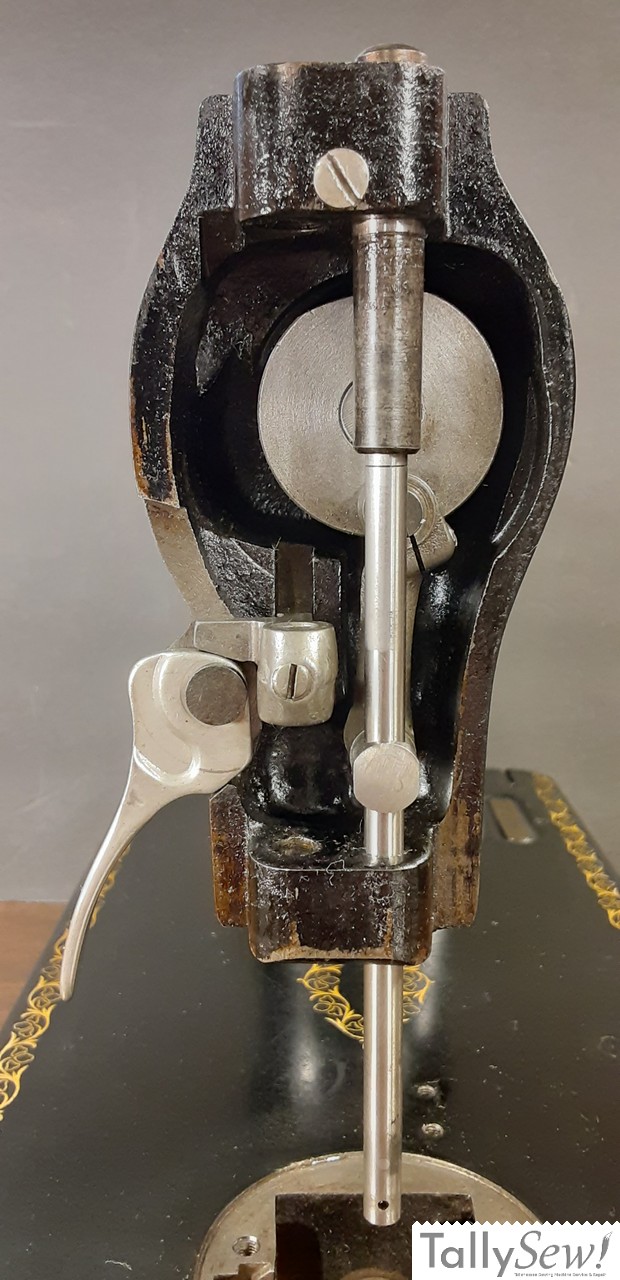
Put the presser bar lifter hinge stud through the hole in the presser bar lifter and then insert it into the machine with the flat on the presser bar lifter hinge stud facing the back of the machine. Screw the presser bar lifter hinge stud set screw in so that it clamps the presser bar lifter hinge stud in place. The presser bar lifter should move freely, but it shouldn’t wiggle back and forth. If it wiggles back and forth then loosen the set screw and gently press on the head of the hinge stud and retighten the set screw. If the presser bar lifter drags as you lift or lower it then loosen the set screw and wiggle it a little to loosen the hinge stud. Gently press on the head of the hinge stud and retighten the set screw.
Installing the presser bar
Place the presser bar spring bracket with the set screw facing out and the guide fit into the slot in the machine. The little arm will rest on the presser bar lifter.
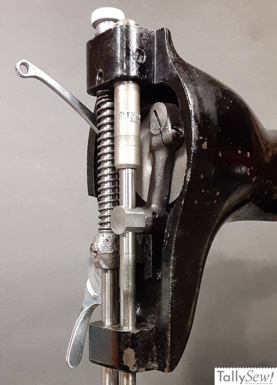
Slide the presser bar in from the top with the flat facing away from the handwheel end of the machine. Snug down the set screw, but don’t go crazy since it will be adjusted later. I have it a little too high in the photo above, it will be a little closer to even with the bottom of the needle bar at it’s lowest point.
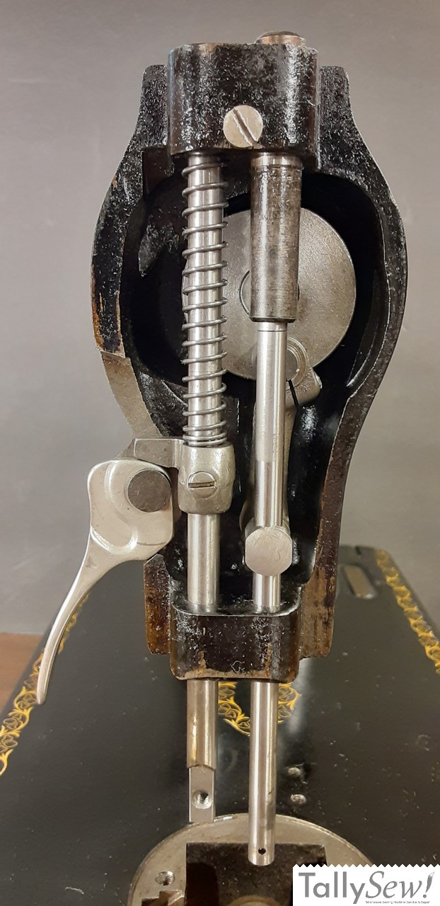
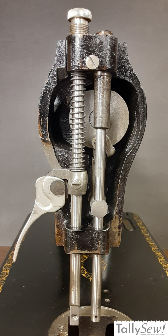
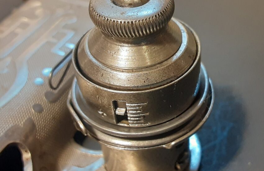
Slide the presser bar spring onto the presser bar shaft. Place the presser bar spring washer on top of the presser bar spring, then install the pressure regulating thumb screw. Run the pressure regulating thumb screw about half to three quarters of the way down.
Installing the thread take-up lever
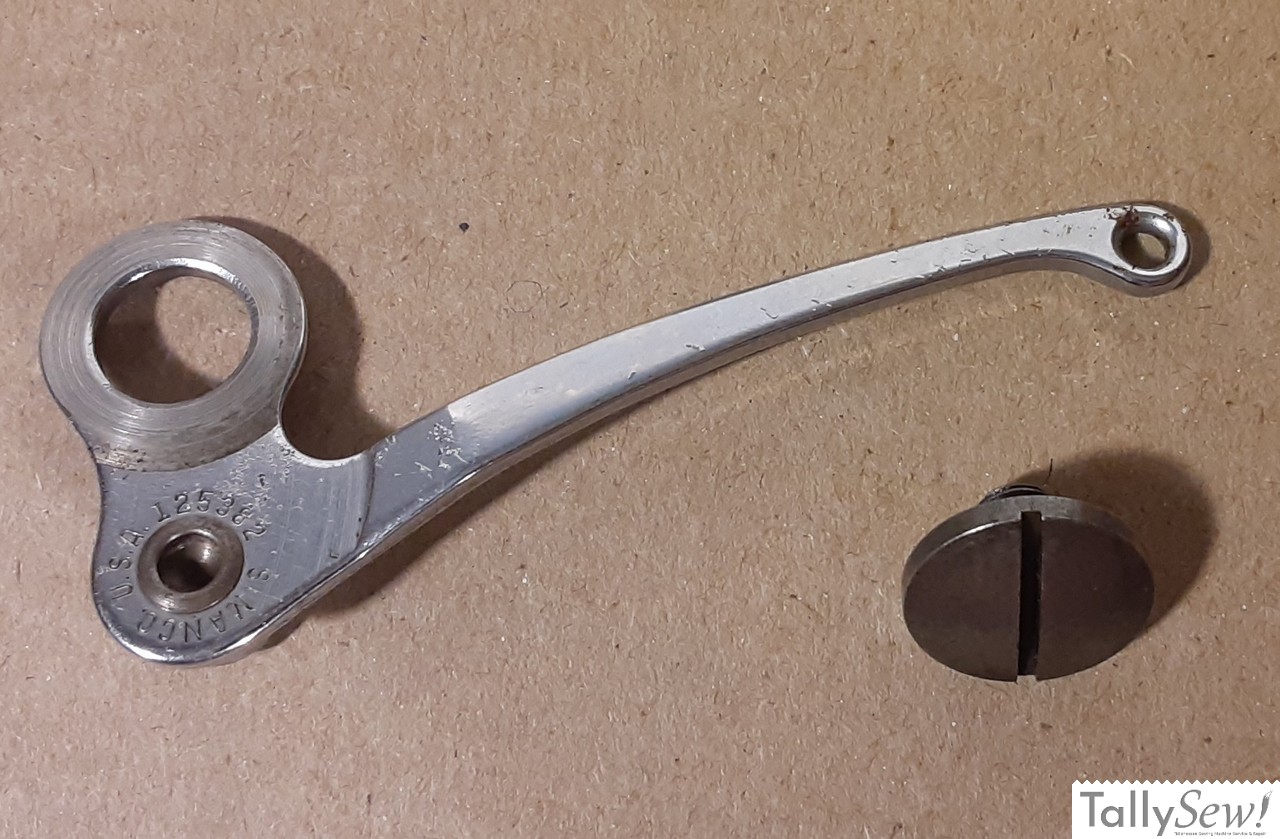
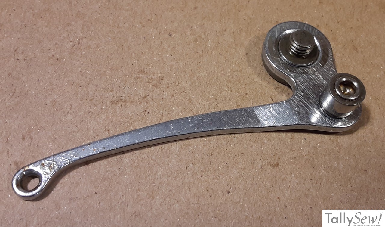
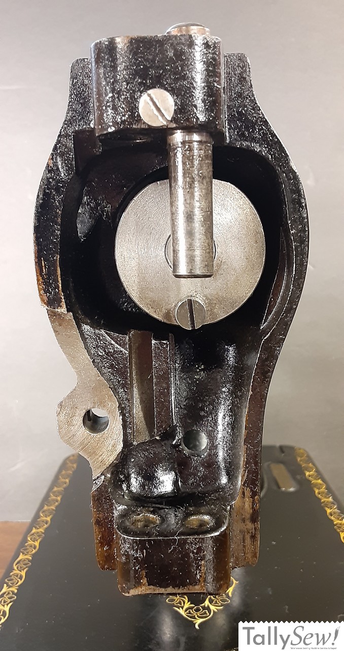
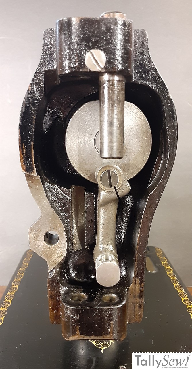
Thread take-up lever and thread take-up lever hinge screw. Note the bearing just below and to the right in the second image. This bearing will fit inside a groove on the side of the thread take-up lever cam on the end of the main shaft.
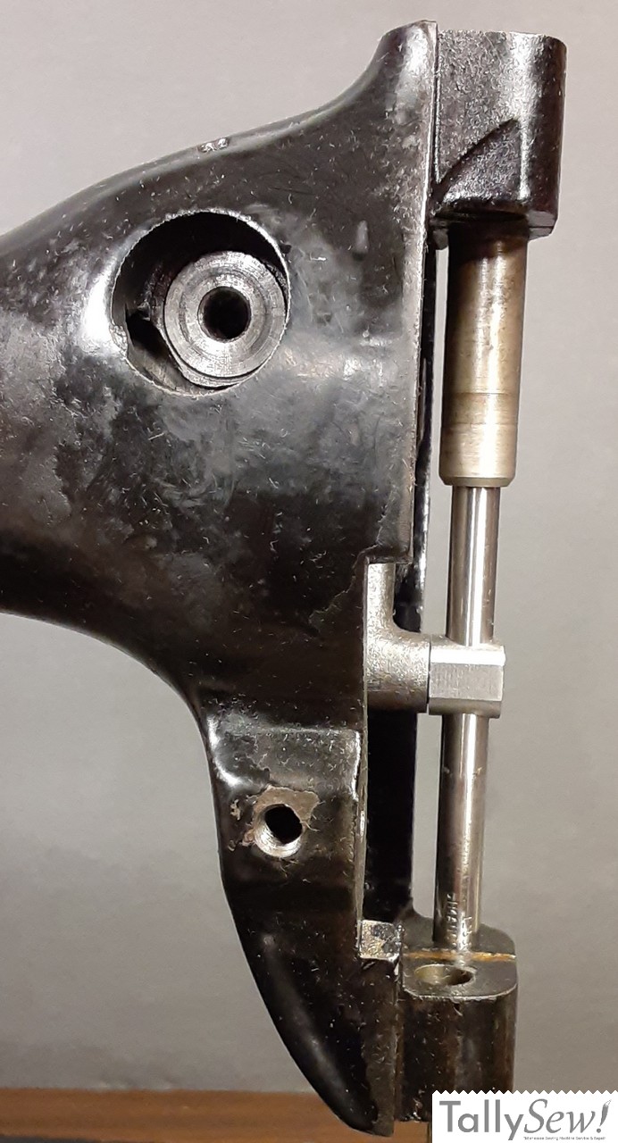
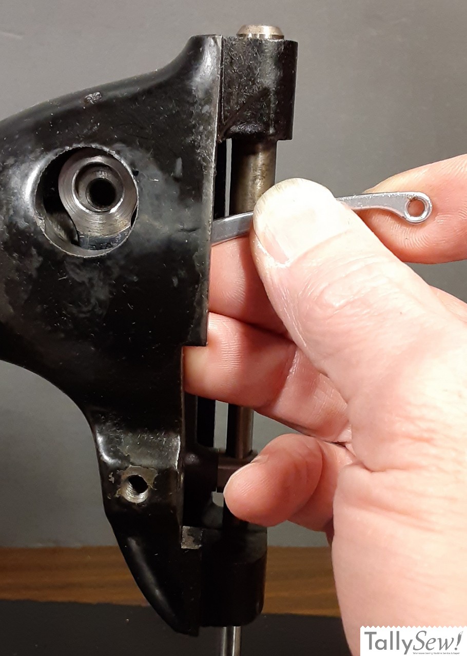
Insert the thread take-up lever bearing in the groove on the side of the thread take-up lever cam and align the holes for the lever hinge screw. Install the thread take-up lever hinge screw making sure that the shoulder of the hinge screw is seated all the way in and not pinching the take-up lever. Once installed, turn the handwheel a couple of times to be sure the take-up lever moves up and down properly.
That’s all for now, Keep an eye out for new articles on how to adjust the installed parts soon.
Related Articles
Replace a broken Shuttle Driver Cushion Spring
The broken shuttle driver cushion spring on my 1932 Singer model 15-91 The first thing I should mention is that you do not need to
Singer 15 series shuttle race
Removing the shuttle race assembly is a pretty simple process

Singer 15 series bottom end
The Singer Model 15 (in this case a 1932 Singer 15-91), with the bottom end roughed in. This article is about getting the parts in

Singer 15 series feed and lift verticals
The two main assemblies found in the pillar of the machine. Crank connecting rod (top), and feed forked connection and feed regulator assembly parts.
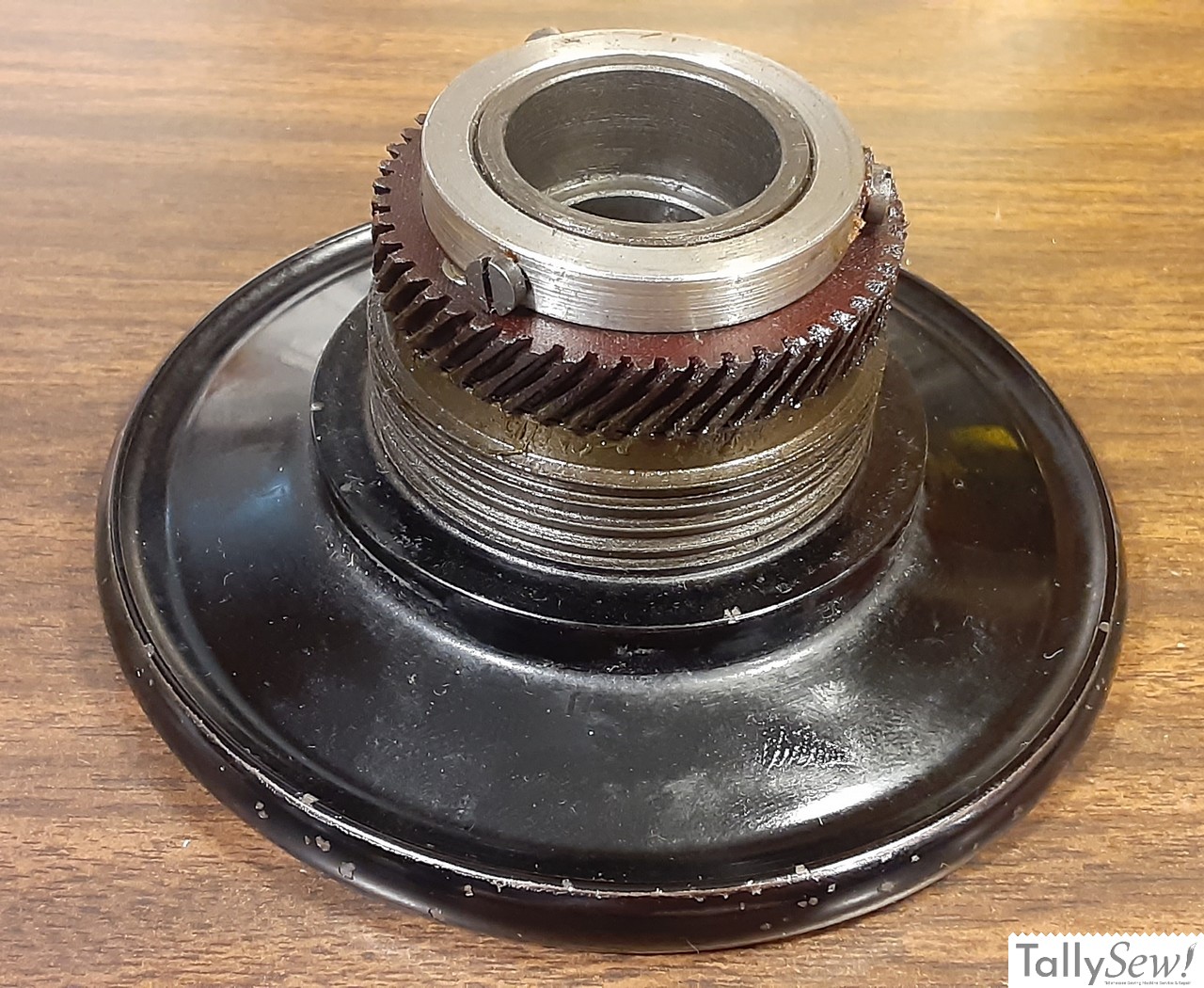
Singer 15-91 and 201-2 handwheels
The handwheels found on Singer 15-91 and 201-2 sewing machines are a little more complicated than they seem at first glance. I’m going to start

Singer CAT.-S4 lamp
The Singer lamp model CAT.S-4 was used on several Singer sewing machine models. It was usually black, but was also produced in green, and in