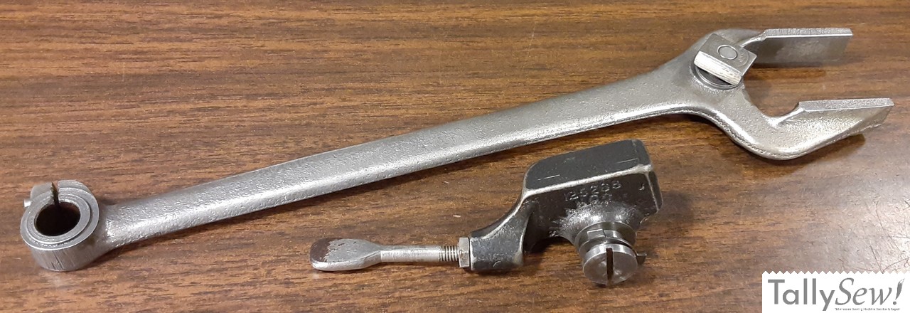
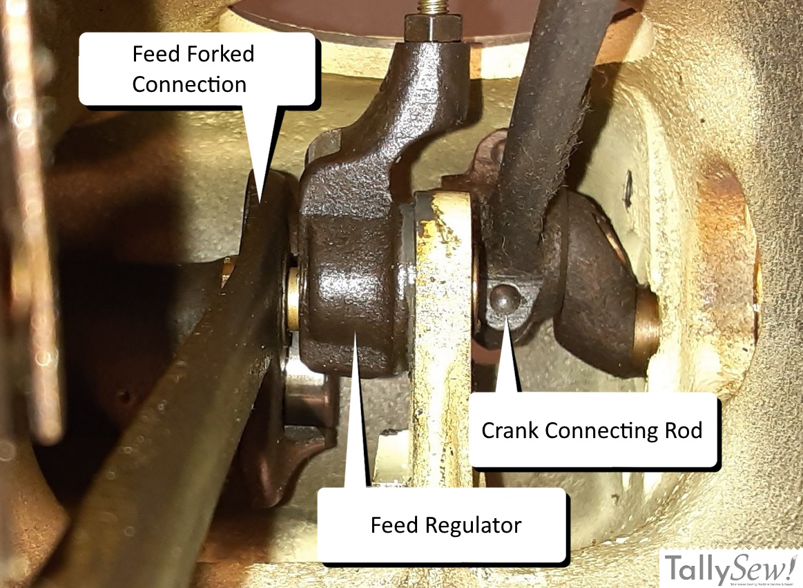
Singer 15 series feed and lift verticals

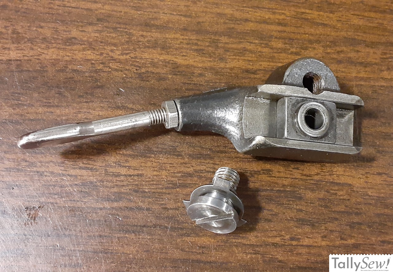
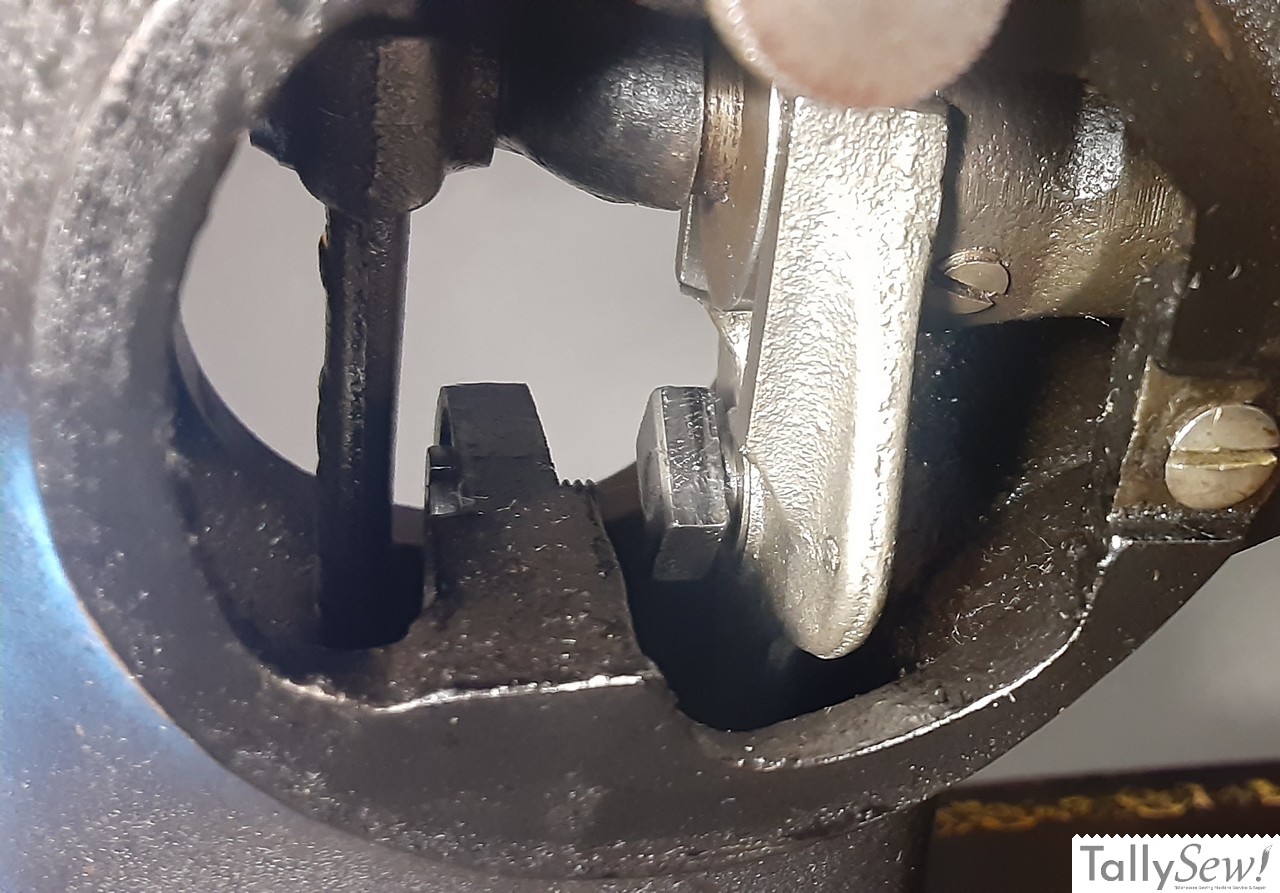
The two main assemblies found in the pillar of the machine. Crank connecting rod (top), and feed forked connection and feed regulator assembly parts.
I’m going to start the article by identifying the parts, and the points those parts attach to.
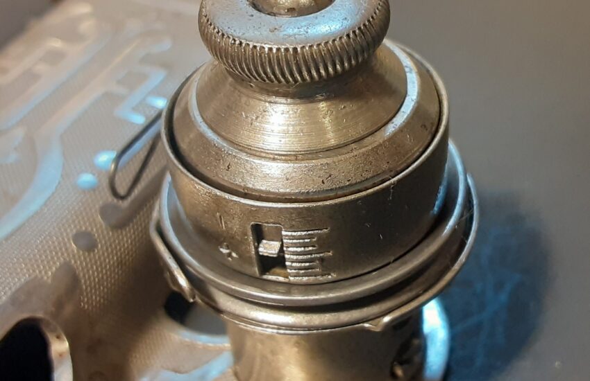
These assemblies are mostly hidden from view, but the model 15 does give you access through the feed regulator cover in the front and the access port cover in the back.
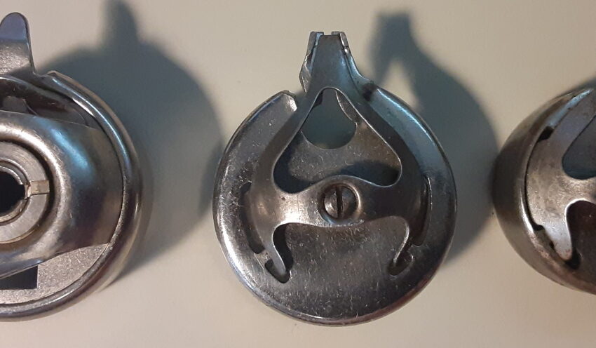
Feed regulator parts
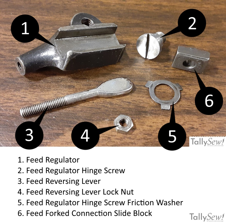
As you can see in the images above, the feed regulator assembly has six main parts along with the feed forked connection link and it’s attachment hardware. The other parts are:
- Feed Regulator
- Feed Regulator Hinge Screw
- Feed Reversing Lever
- Feed Reversing Lever Lock Nut
- Feed Regulator Hinge Screw Friction Washer
- Feed Forked Connection Slide Block
Attachment points
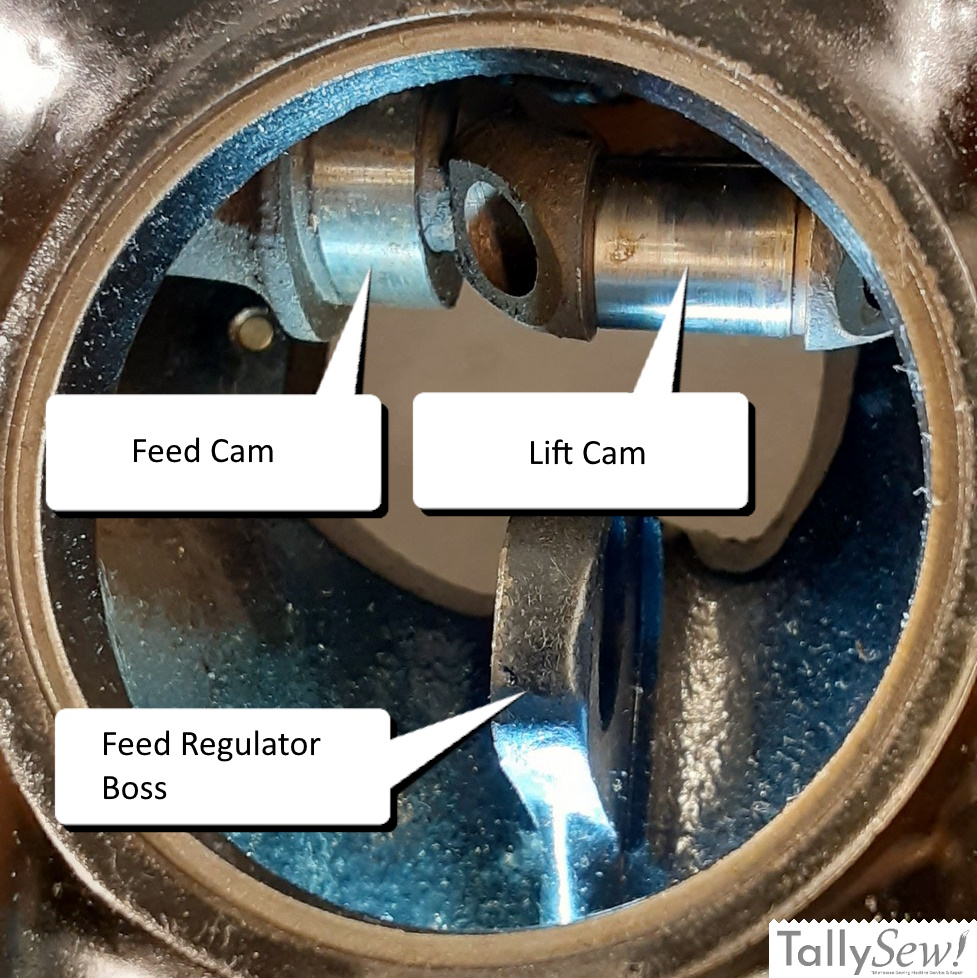
Since this is normally hard to see I’ll go over where the different parts will attach.
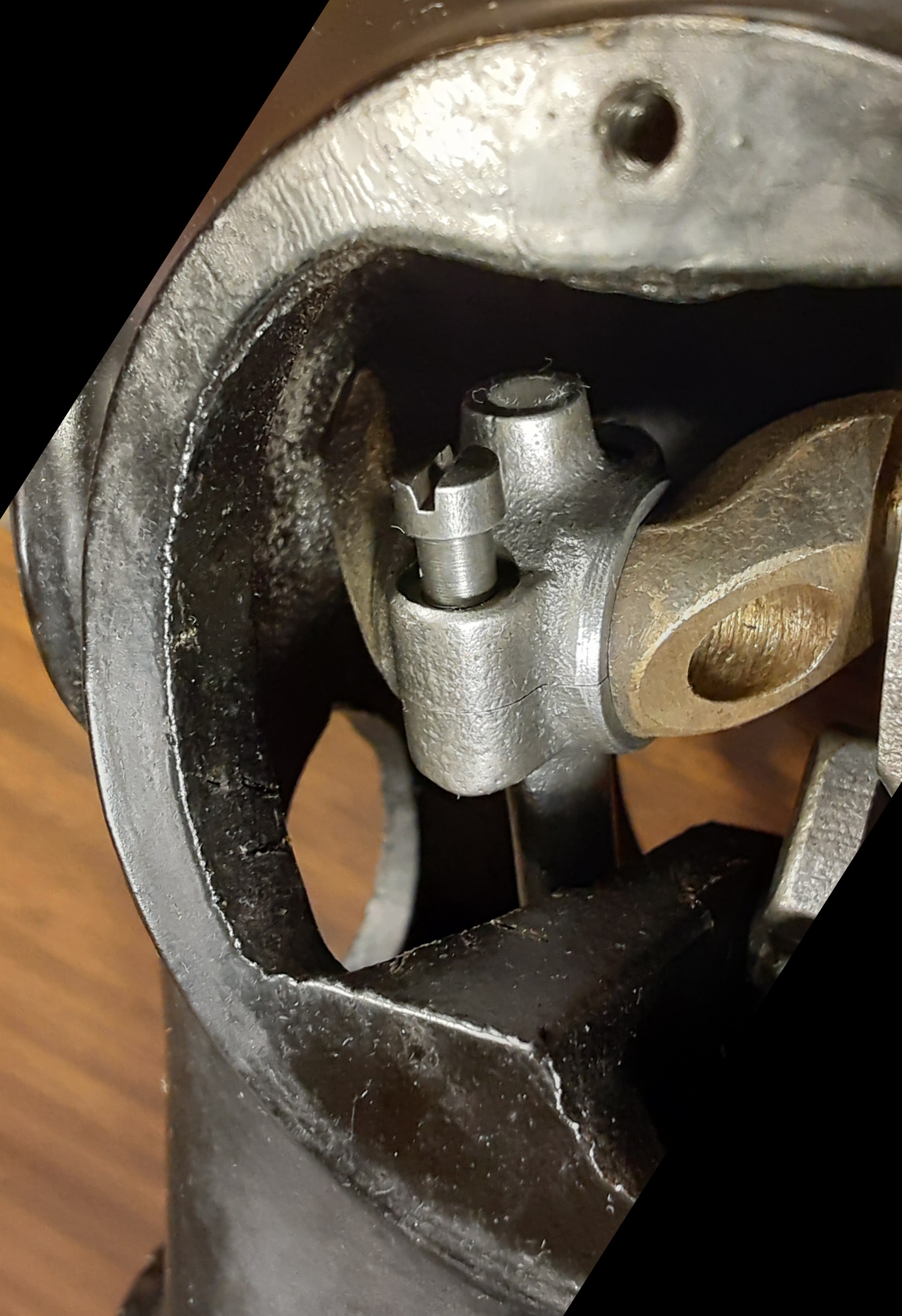
- The forked end of the feed forked connection will go over the feed cam on the crank with the slide block facing the hand wheel and of the machine.
- The large end of the (feed lift) crank connecting rod attaches to the lift cam on the crank.
- The feed regulator fits between the feed regulator boss and the feed forked connection with the slide block in the groove of the feed regulator.
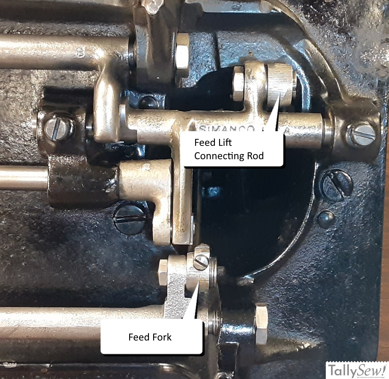
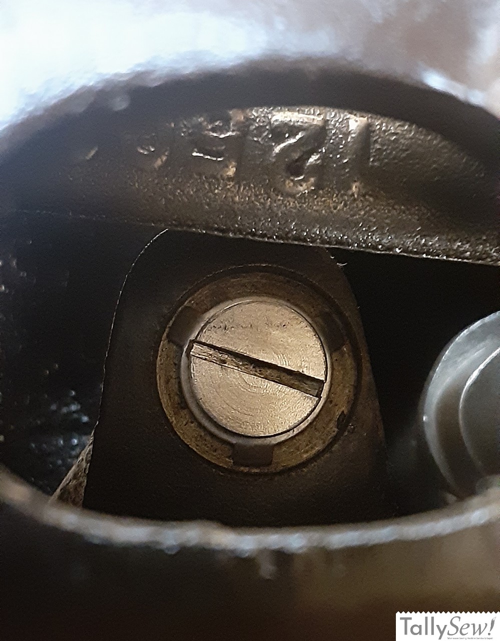
- The small end of the crank connecting rod attaches to the oscillating rock shaft to the right of the boss, and with the large side of the screw hole to the handwheel side of the machine so that the tapered head of the hinge bolt can fit in flush with the surface.
- The small end of the feed forked connection connects to the right of the boss on the feed rocker and is attached with an eccentric bolt.
Installing the feed fork and feed regulator
If you could see inside the machine you’d see that the feed forked connection is attached to the feed rocker and the forked end would hold the feed cam on the main shaft.
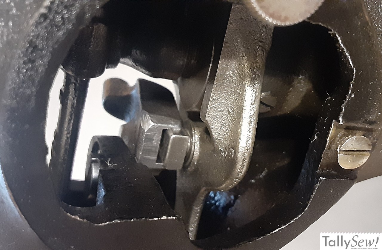
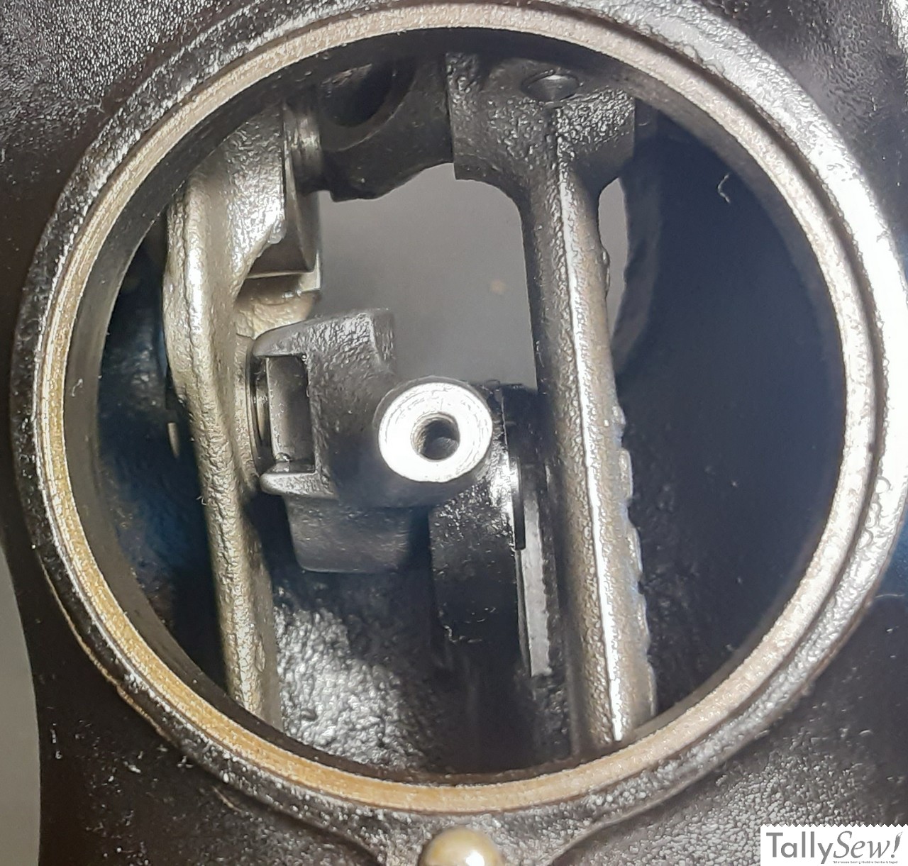
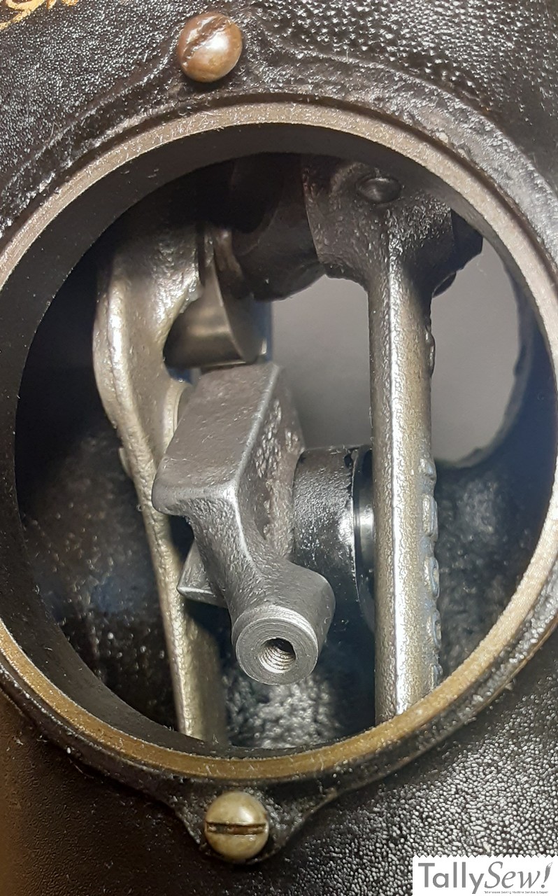

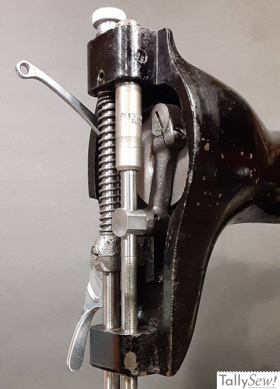
The first three images above are taken from the rear of the machine through the access port.
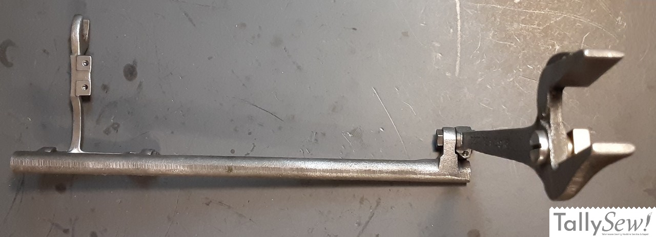
Slide the feed fork, with the feed slider block attached, up through the pillar of the machine until the fork is holding the left cam on the main shaft. Slide the feed regulator between the feed fork and the feed regulator mounting boss, guiding the feed slider block into the groove in the feed regulator. Using a screw starter if available, insert the feed regulator screw with it’s friction washer through the hole below the main shaft on the right end of the machine and screw it into the feed regulator. Now attach the small end of the feed fork to the feed rocker using the eccentric nut and locking nut. Don’t bother making this tight since it will need to be adjusted later.
Crank connecting rod
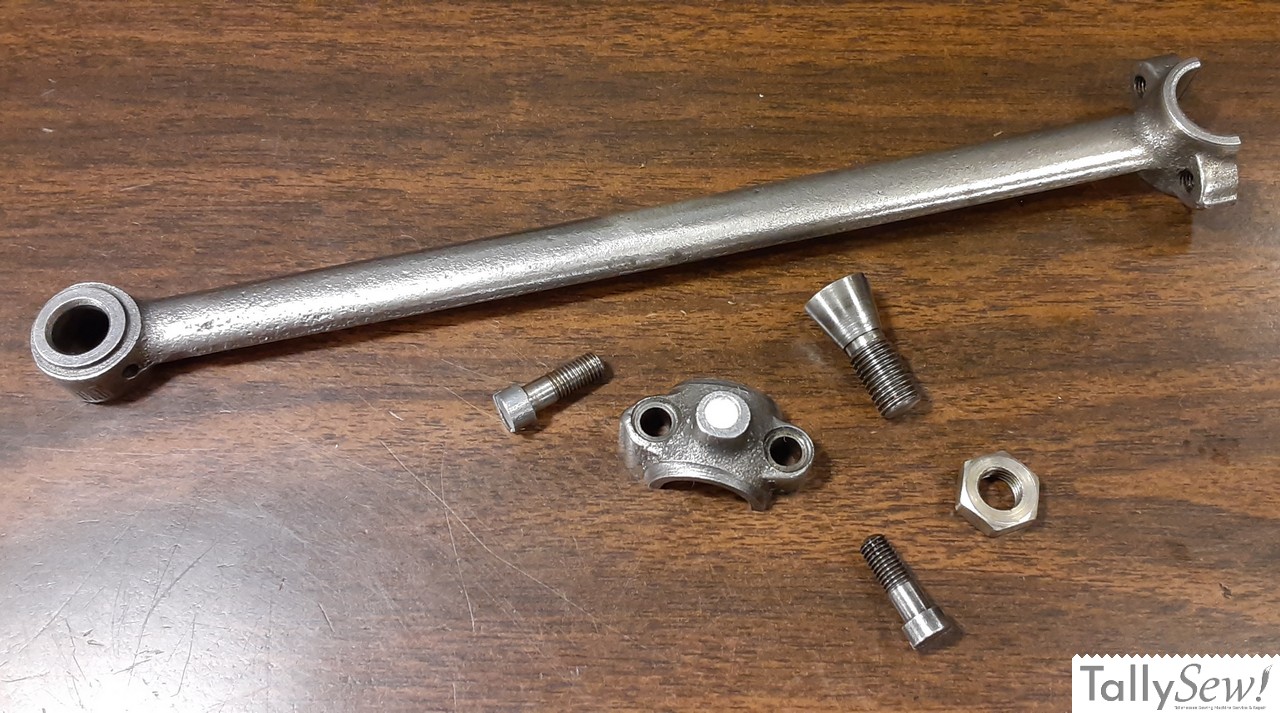
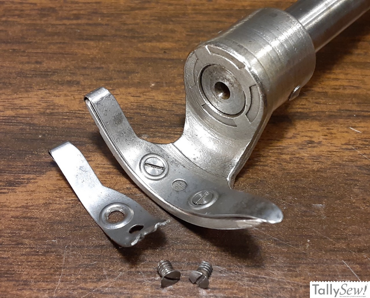
The crank connecting rod assembly consists of the crank connecting rod, connecting rod cap, two connecting rod cap screws, an oil wick that goes in the connecting rod cap, and the crank connecting rod hinge screw and it’s lock nut.
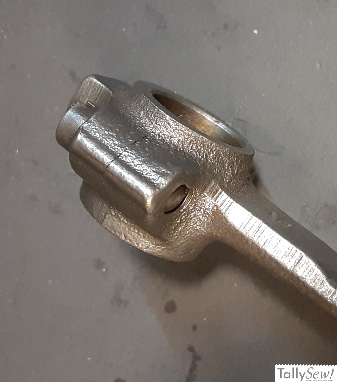
Warning: The connecting rod cap MUST be installed with the rib on the connecting rod and the cap on the same side (see second photo). If you put this together wrong you WILL damage the machine. Also, the connecting rod and cap are a pair. Do not use a cap from another rod or vice versa. Doing so will likely damage the machine.
Installing the crank connecting rod

Before you start this process, make sure you add oil to the oil wick and to the bearing surfaces on both ends of the connecting rod.
With the machine laying on it’s back, insert the connecting rod into the pillar through the space above the feed rock shaft. The alignment ridge for the connecting rod cap will be facing the front of the machine, and the large side of the pivot bolt hole on the small end of the connecting rod will be facing the handwheel (right) end of the machine. Put the open end of the connecting rod onto the main shaft and hold it there as you carefully put the machine right side up and turn it so that the back of the machine is facing you. Move the crank shaft down so you can see to place the connecting rod cap in place (alignment ridge to the front of the machine), and screw one of the connecting rod cap screws in by hand (do not tighten). You will need to put the other connecting rod cap screw in place mostly by feel, and screw it in as best you can with your fingers.
You can reach the tops of the connecting rod cap screws through the oil hole in the top of the machine. Look down and through the oil hole to see when you are aligned with one of the connecting rod cap screws, then snug it down. It’s best to tighten a little, then do the other one, going back and fourth a few times before each connecting rod cap screw is tight.
Now lay the machine on it’s back again and screw in the connecting rod pivot bolt (tapered head screw), and it’s locking nut. You can leave this a little on the loose side at this point since you will may end up needing to move it around when you make your final adjustments.
That’s all for this article. You can find more related articles below, and I’m adding new ones all the time.
Related Articles
Singer 15 series needle bar box
The Singer model 15 series machines is simple and robust. I’m going to give you an overview of how to assemble the needle, and presser
Replace a broken Shuttle Driver Cushion Spring
The broken shuttle driver cushion spring on my 1932 Singer model 15-91 The first thing I should mention is that you do not need to
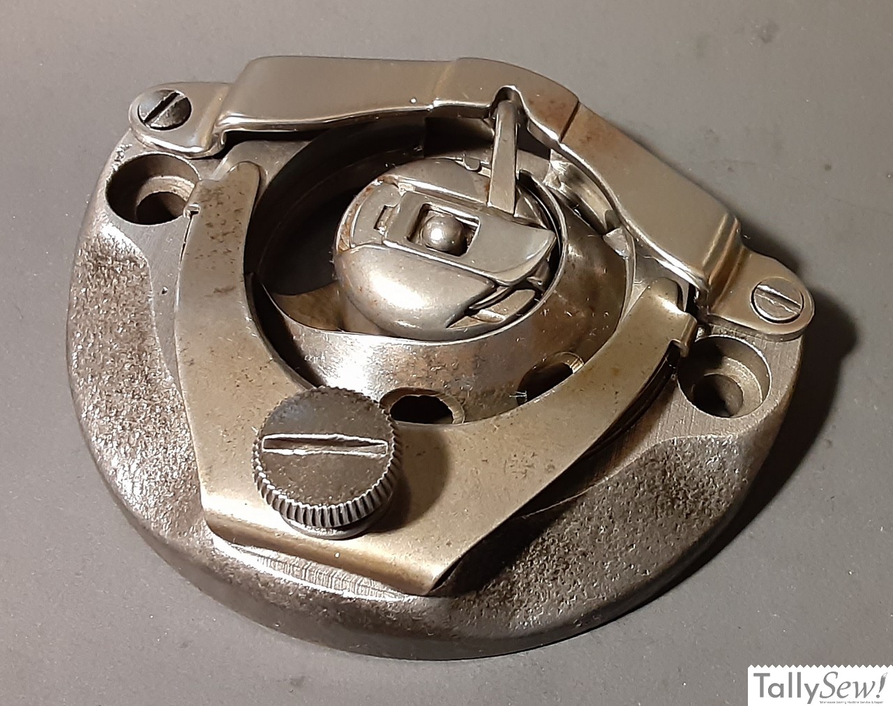
Singer 15 series shuttle race
Removing the shuttle race assembly is a pretty simple process

Singer 15 series bottom end
The Singer Model 15 (in this case a 1932 Singer 15-91), with the bottom end roughed in. This article is about getting the parts in
Singer 15-91 and 201-2 handwheels
The handwheels found on Singer 15-91 and 201-2 sewing machines are a little more complicated than they seem at first glance. I’m going to start

Singer CAT.-S4 lamp
The Singer lamp model CAT.S-4 was used on several Singer sewing machine models. It was usually black, but was also produced in green, and in