Kenmore 117 series tensioner removal

Removing the tensioner from a Kenmore 117.959 Rotary sewing machine.
This article assumes that you have already removed the needle bar box from the machine. If you haven’t removed it yet, please refer to Kenmore 117 series needle bar box for instructions.


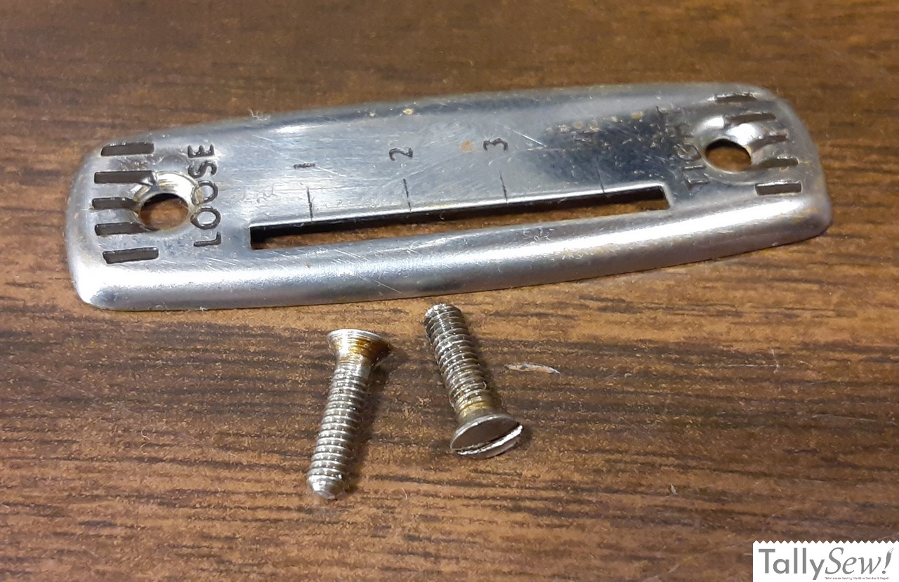
- Remove the thread take-up lever hinge cover by removing the top screw holding the tension adjuster cover plate.
- Remove the lower screw from the tensioner adjuster plate.
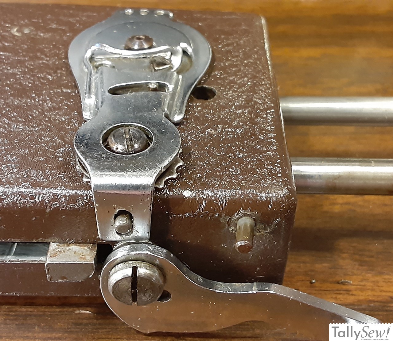
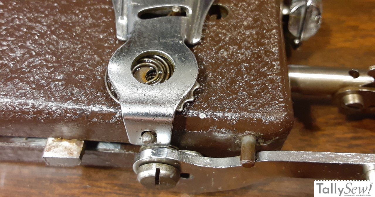
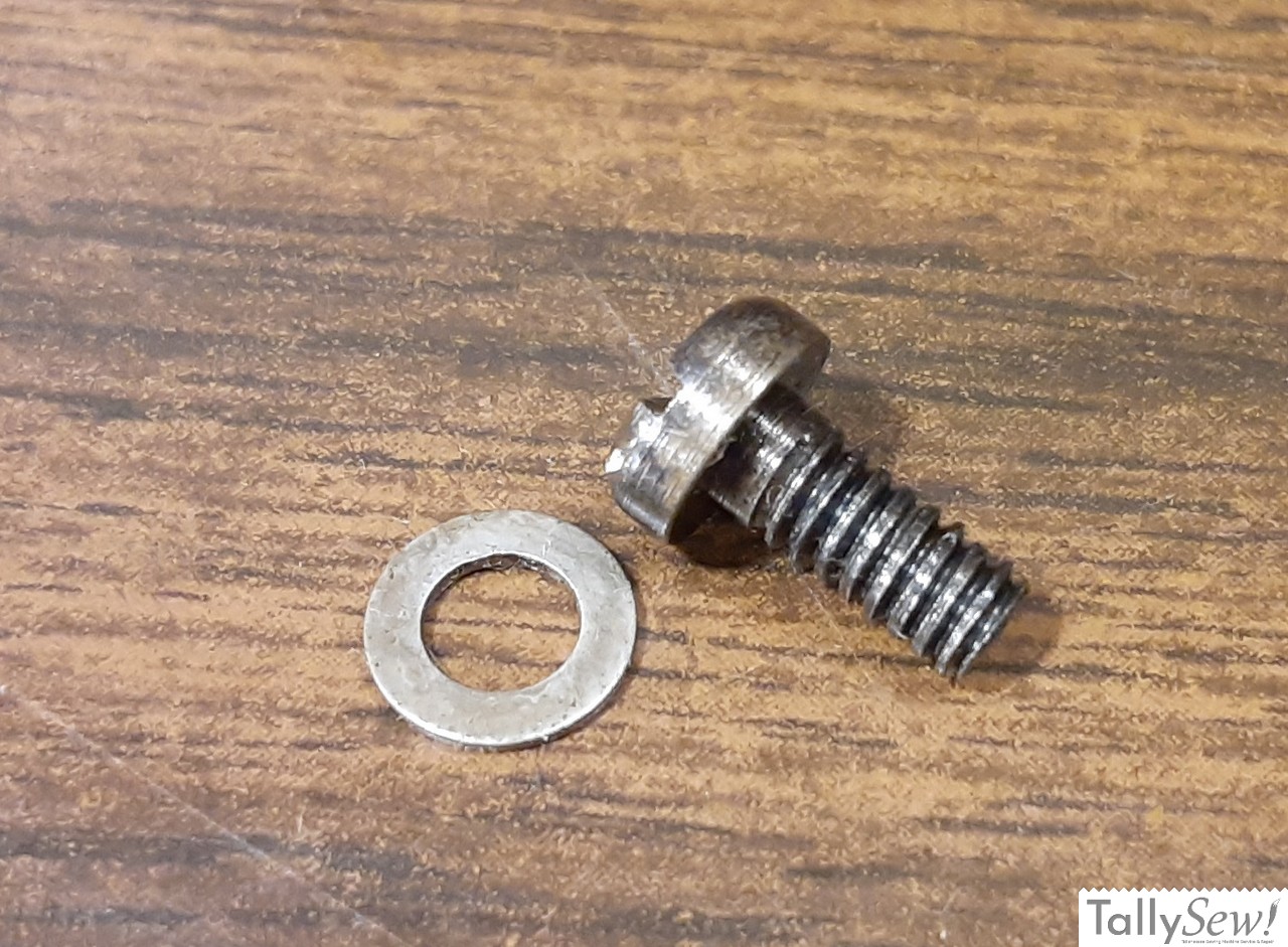
- Remove the screw and washer from the center of the tensioner.

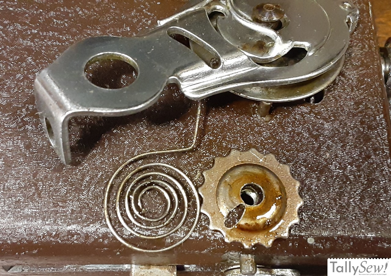
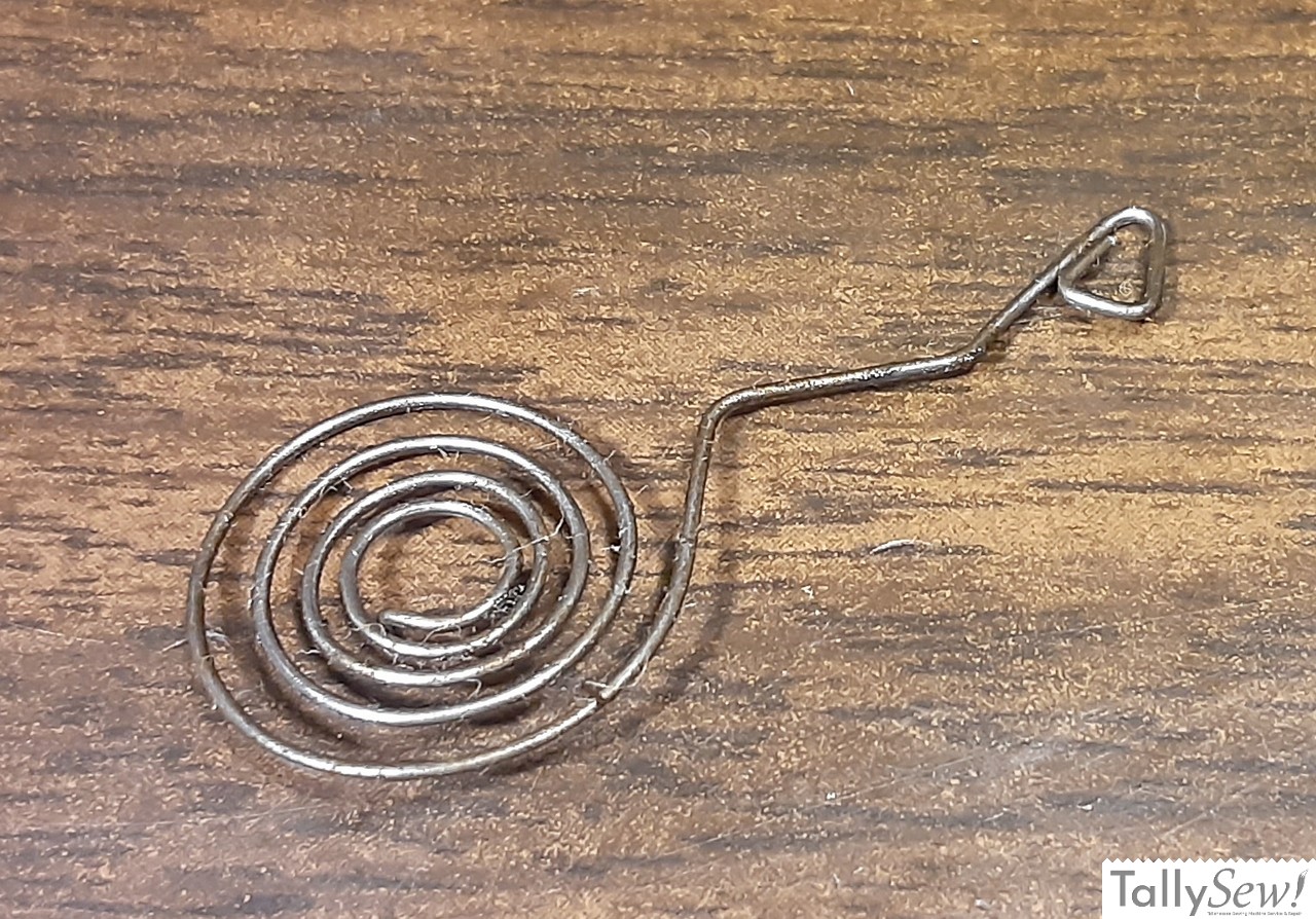
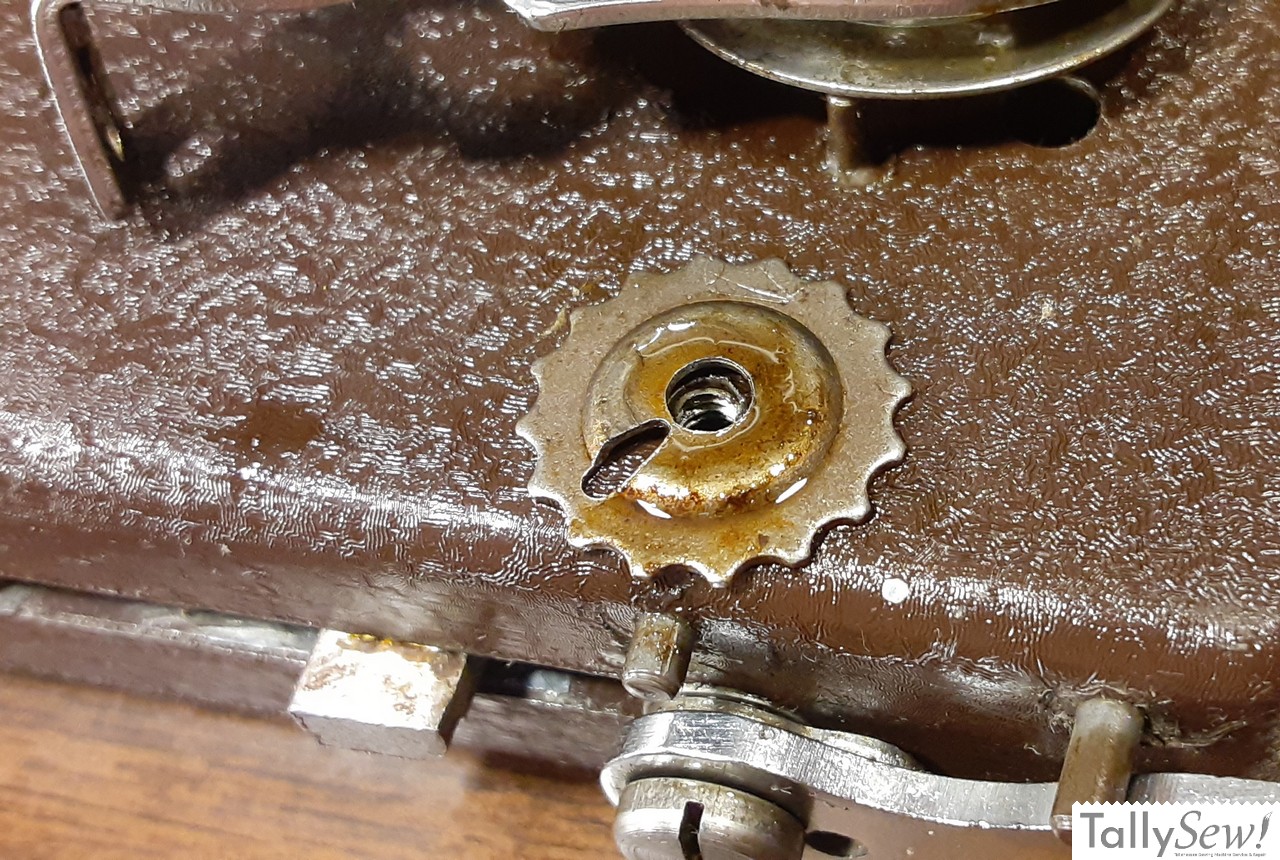
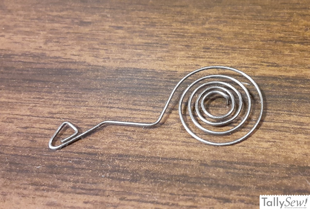
- Remove the clock spring.
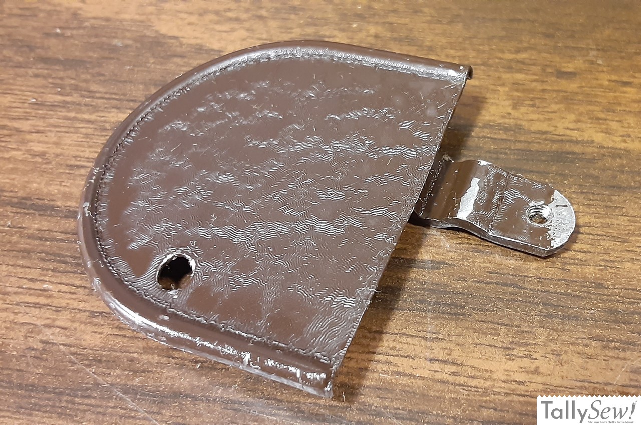
- Remove the take-up spring adjustment cog/washer.
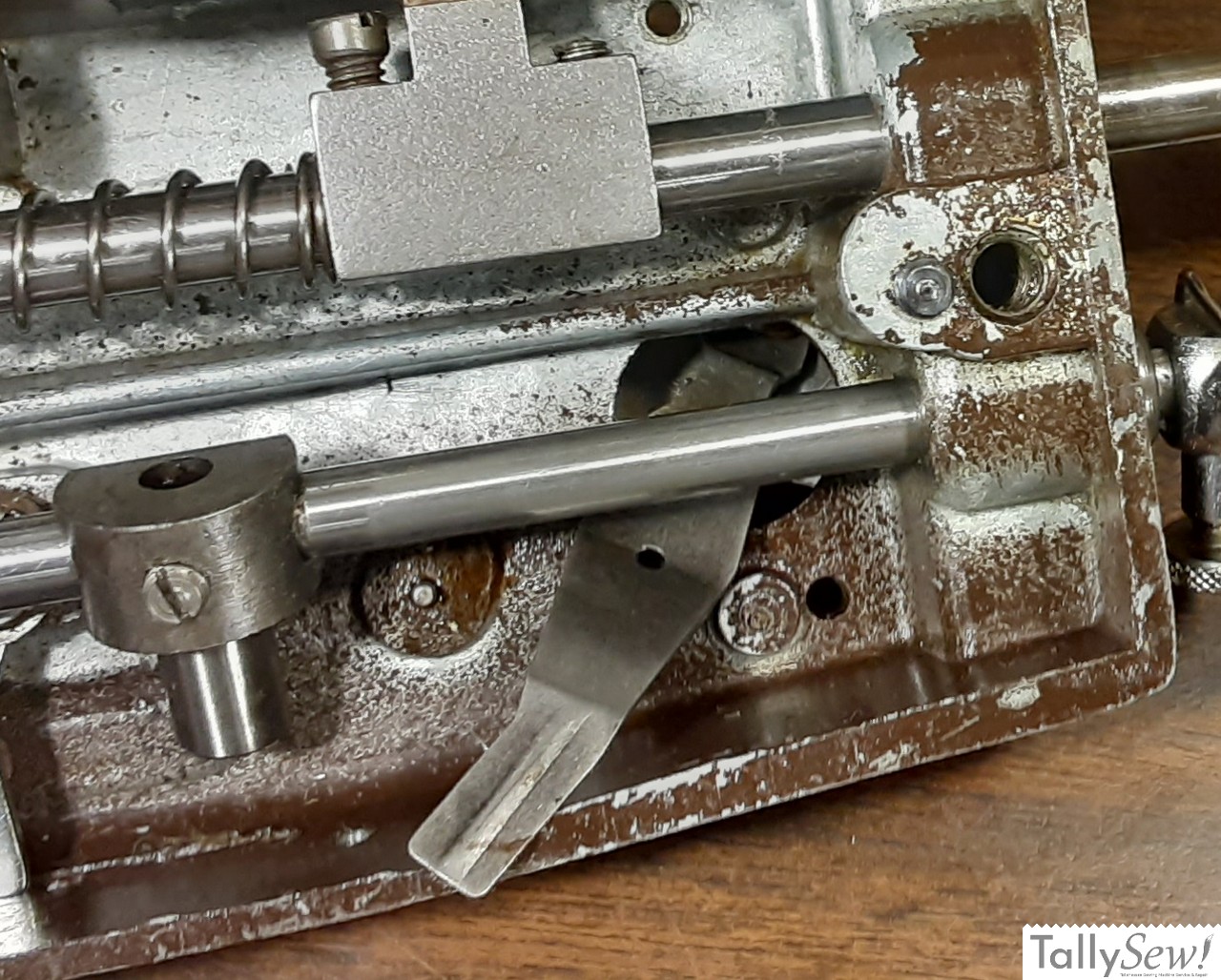

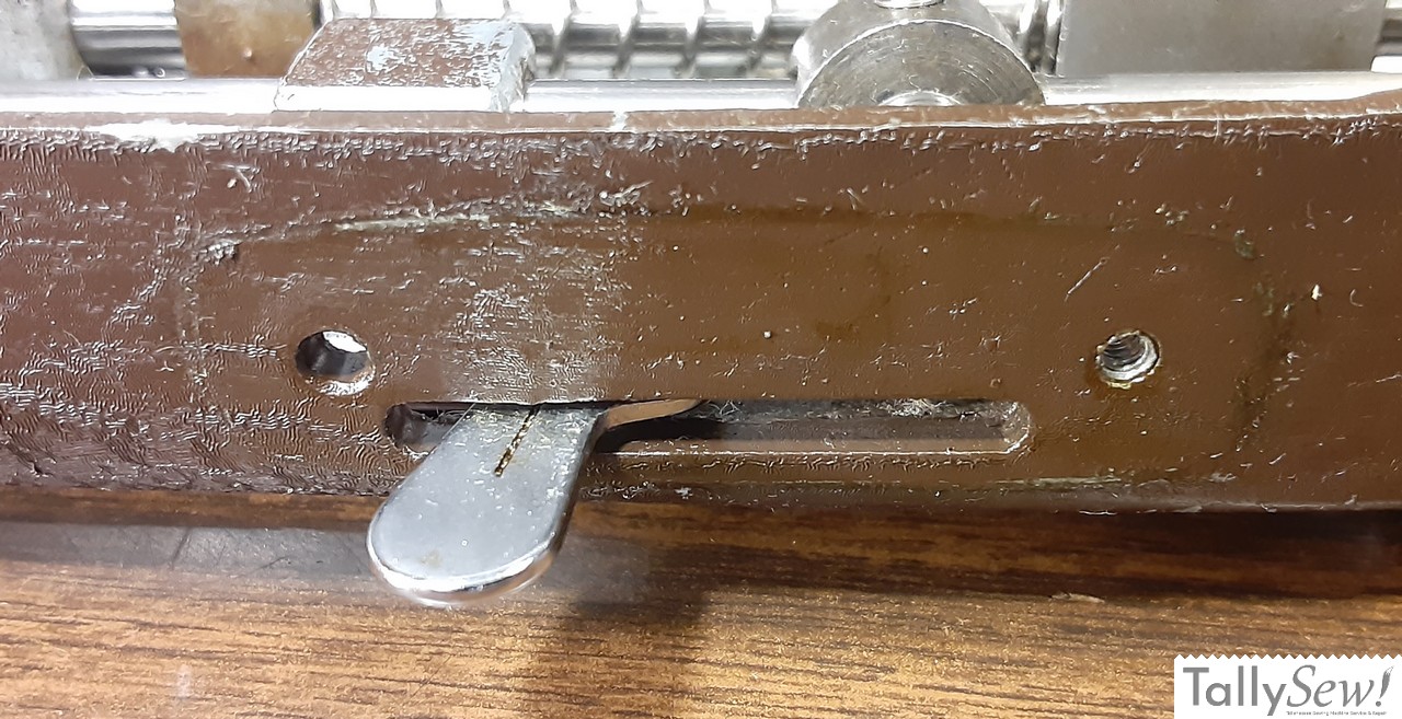
- Turn the needle Bar Box over so that you’re looking at the inside and push the tension adjuster lever all the way to the top of its slot.
- The tension adjustment flat spring will now be free.
- Put the Needle Bar Box on its edge so you can hold the tensioner parts on the front and the tensioner flat spring inside the needle bar box.
- While holding the tensioner body, feed the tensioner spring out to the front of the box through the hole.
- This will give you access to all of the tensioner parts except for the tensioner adjustment arm.
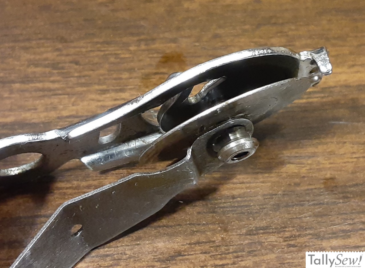

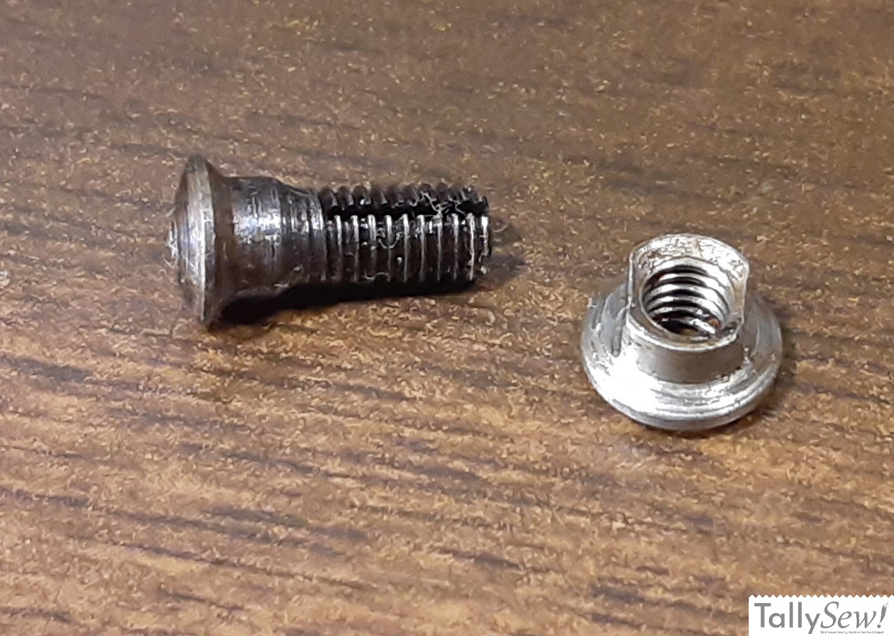
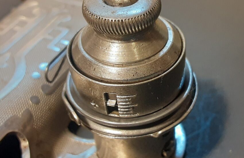
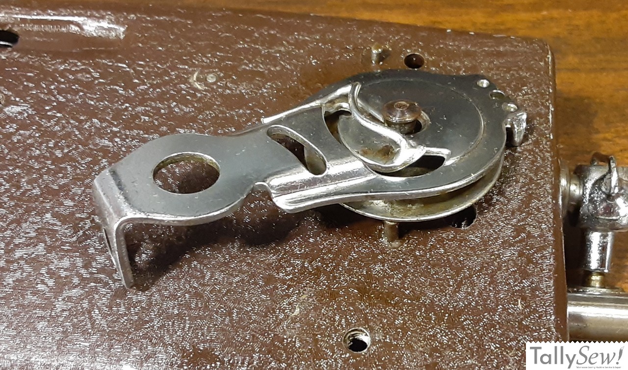
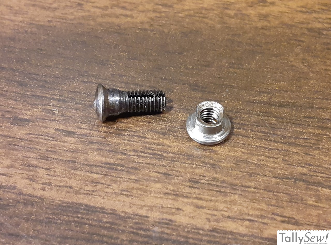
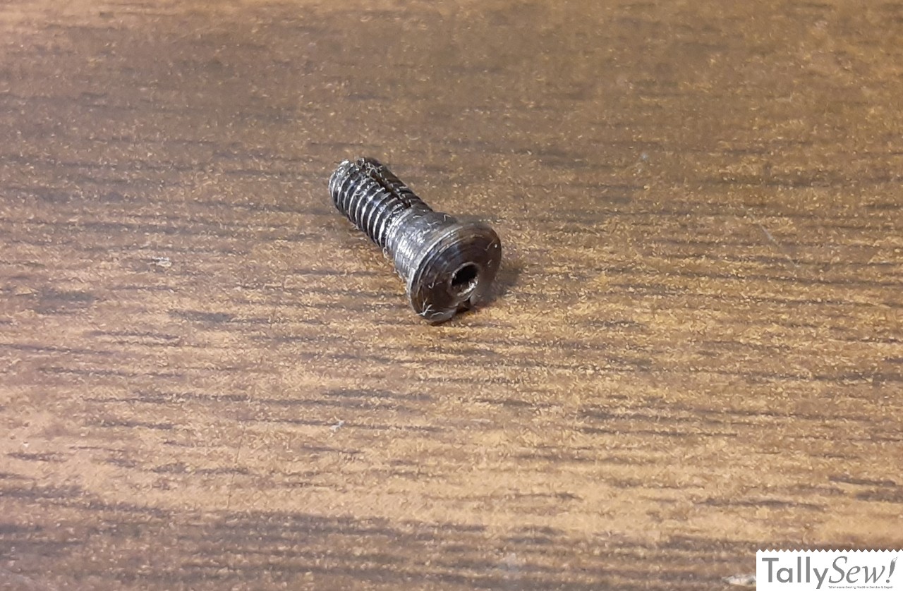
- To disassemble the tensioner front, disc, and flat spring, you’ll need to unscrew the connector.
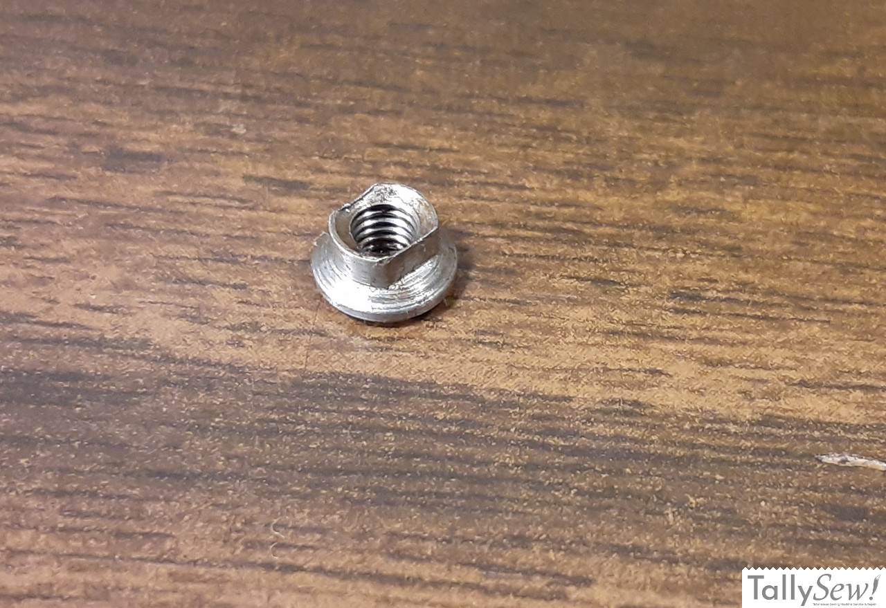
- On the inside face of the connector, you’ll find a screw slot, and that the nut has two flat sides on it.
- Count how many threads are exposed inside the nut… You’ll need this information to put it back together.
- Use needle-nose pliers or some other appropriate tool to grasp the flats on the nut and use a small flathead screwdriver to screw the center section clockwise until it releases from the nut.

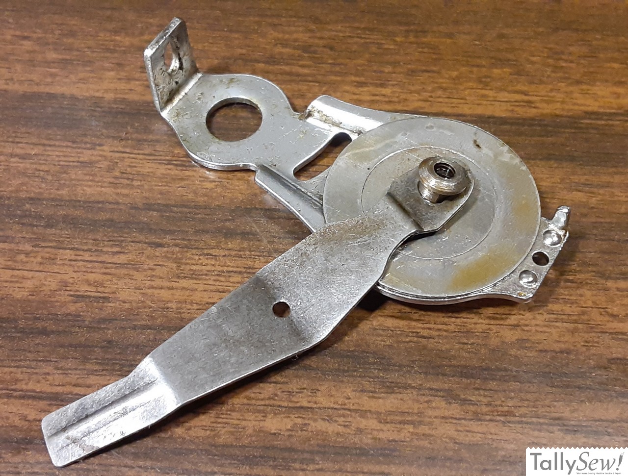
- Now you have all of the tensioner parts removed except for the tension adjustment arm. Removal of the tension adjustment arm requires the removal of the needle bar, and that’s beyond the scope of this article.
Parts identification


I’ve added the names to the captions for the images above, but I’m also adding them here in case you can’t see them on your device:
- Tension plate
- Tension disc
- Tension spring inside of face
- Screw and washer
- Auxiliary/Clock spring
- Adjusting Washer
- Split screw and nut with flats
- Tension indicator plate and screws
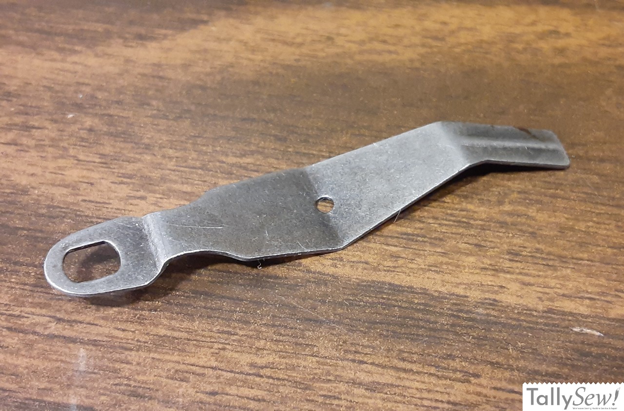
- Tension adjustment arm and hinge screw
The best resource I could find for the actual parts names comes from the “White Rotary Book 11”, and that book is for much earlier machines than this one. I think the names that I’ve found and used are close enough for this conversation, but If I find a better resource later I will update the information here.