Singer, 2 cord, 4 wire, bakelite, female, three post plug
Today I’m going to show you how to wire the Singer, 2 cord, 4 wire, bakelite, female, three post plug. This is the plug you connect to the socket usually found at the base of the machine below the handwheel. This article is for the Singer bakelite plug that has both a power cord and a control cord.
- This article is about a specific part and for a specific machine, If you’re working on a different part, then you should not assume what you’re working on is wired the same way.
- This project requires a high level of manual dexterity and visual acuity.
- If done incorrectly this project can lead to electrocution, and/or fire, leading to injury and/or death.
- You should have a working understanding of alternating current at household voltages, and be comfortable using a soldering iron.
- If you aren’t qualified or capable to do this project I advise you to simply purchase a replacement power and control unit from one of the many stores that carry them.
- In truth it’s probably less expensive and safer to purchase a new assembly than to rebuild the vintage parts.
- If you move forward on this project you do so at your own risk.
Wiring diagram
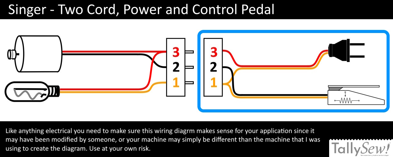
Note: There are a lot of different wiring configurations and plug designs, so make sure you’re using the information relevant to your machine. If you’re unsure in any way please take your machine to a qualified technician.
I also have a tutorial on how to wire the plug for the Singer 1 cord 2 wire bakelite female three post power cord plug.
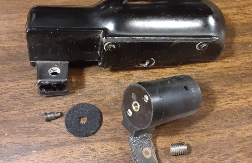
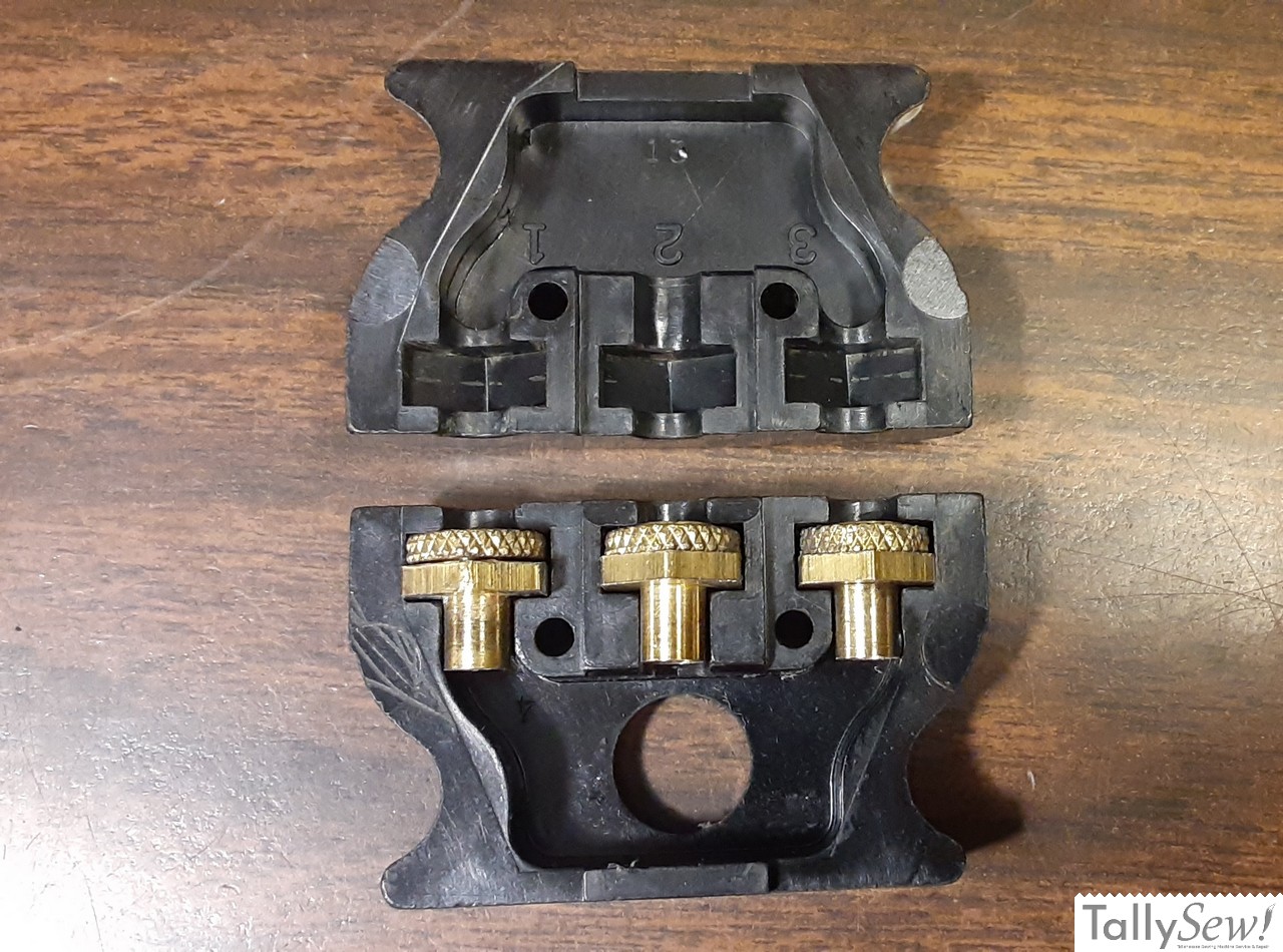
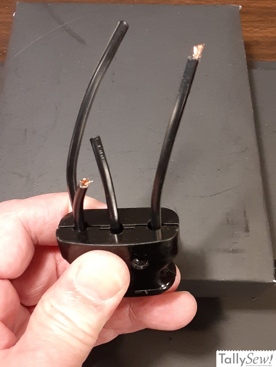
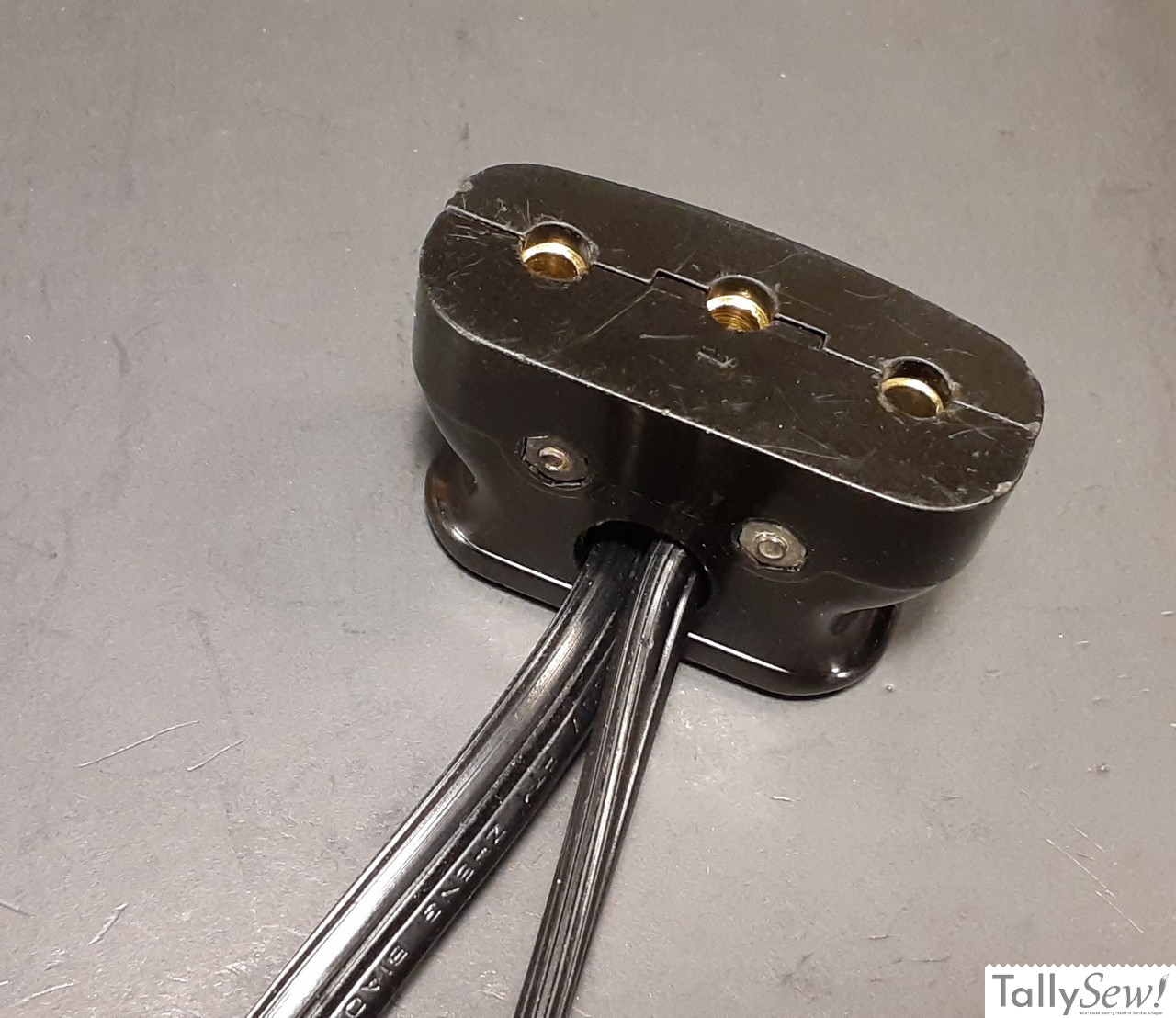
Plug parts

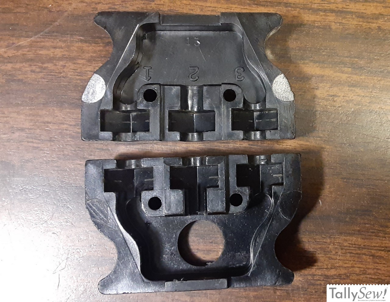
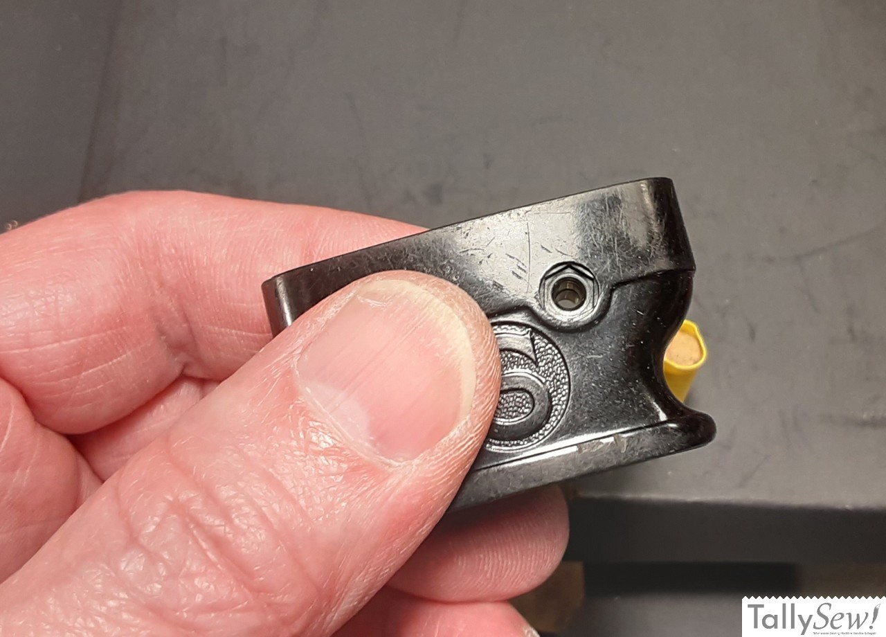
The two cord, four wire power plug has a round hole rather than a slot for the cord to go through.
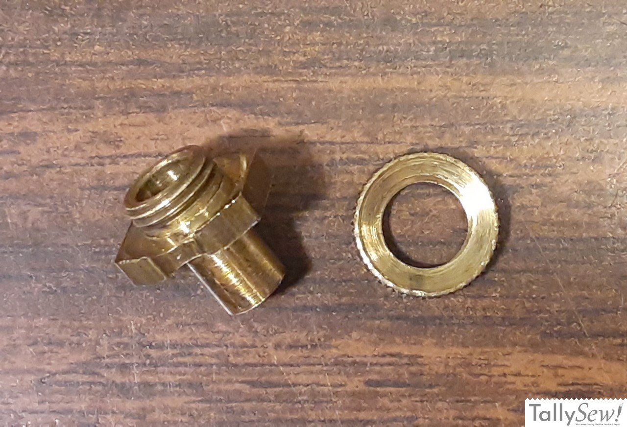
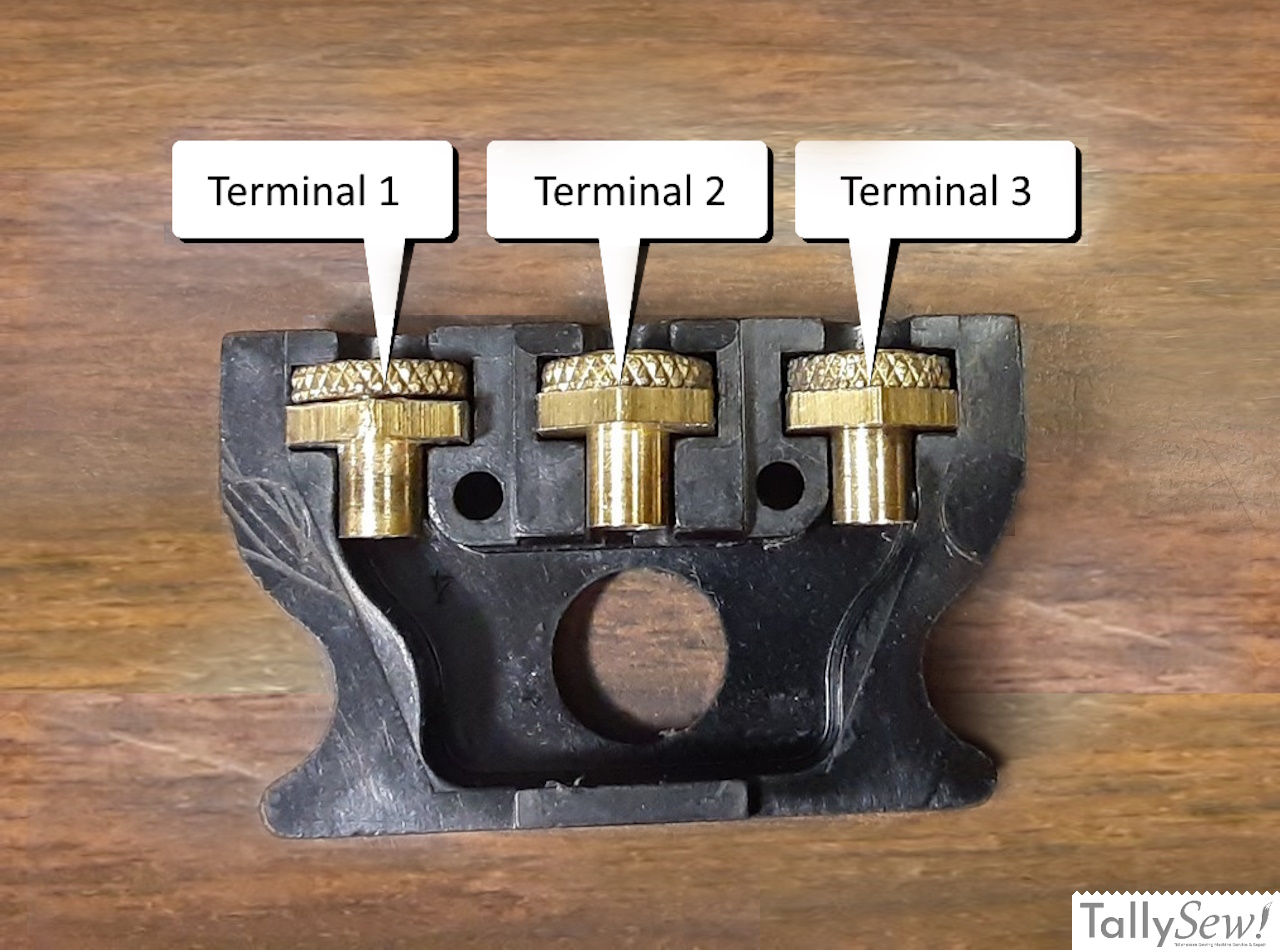
The plug should also include thee terminals, each one made of two parts. A circular nut that is flat on one side and concave on the other, and the terminal body that the nut can screw onto.
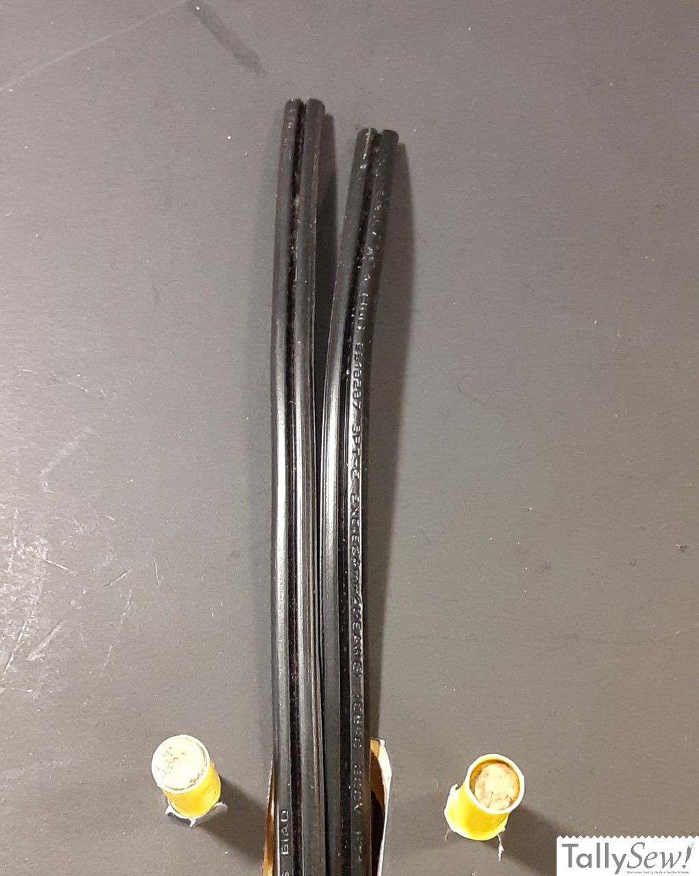

I’m using 18/2 SPT-2 lamp wire for this power and control cord, and that’s the wire size and type generally used for vintage sewing machine power and motor control cords. Start by deciding what length of power cord you want to end up with and add 8 to 10 inches to account for the wire that will be stripped and for the underwriters knot inside the plug we’re looking at now.
Preparing the cords and wires
- Choose the cord you want to act as the power cord and remove ⅛ inch of the insulation from each wire on that cord.
- This makes it easier to keep track of where each wire goes.
- It’s also a good idea to put a piece of tape on the free end of the power cord so that you’ll know what cord gets a plug and what cord gets a motor control attached to it.
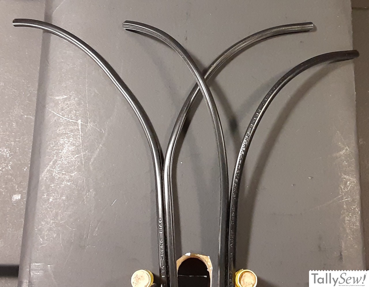
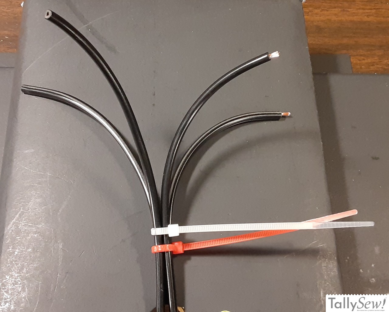
- Lay the cords side by side with the ends lined up together.
- Separate the two wires in each cord six or seven inches, making sure both cords have the wires separated the same amount.
- Facing the curve of each cord away from each other, place the two cords together.
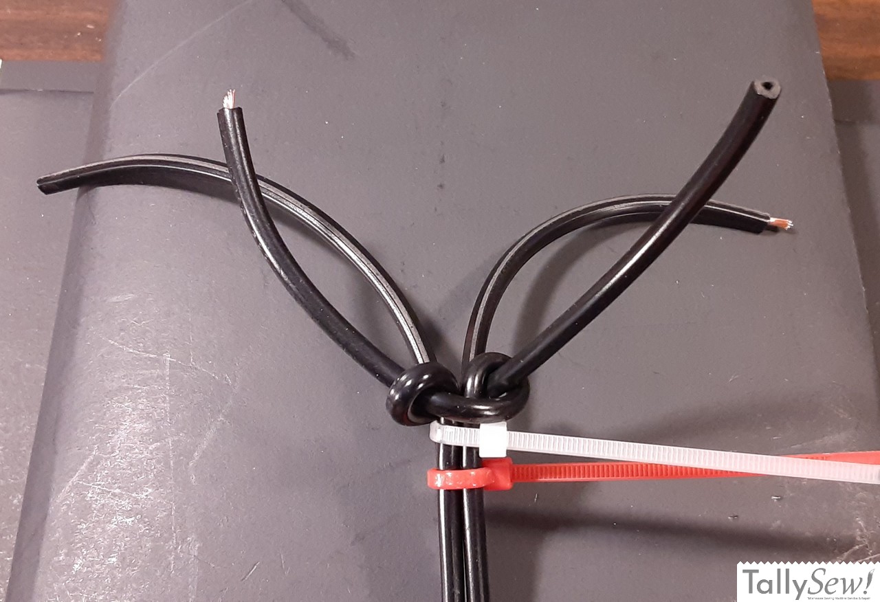
- Use a zip tie to tie the two cords together right at the point where the wires start to diverge from each other.
- Use another zip tie to join one wire from each cord together.
The underwriters knot
An underwriters knot is used to keep wires from pulling loose when they get pulled by the cord. Since using two underwriters knots would take up far too much room inside the limited area inside the plug we need to make one underwriters knot using one wire from each cord so both cords are anchored inside the plug body.
Creating the underwriters knot
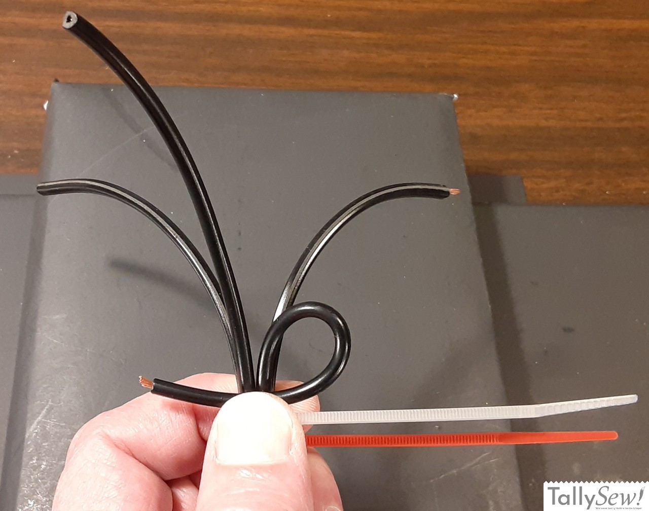
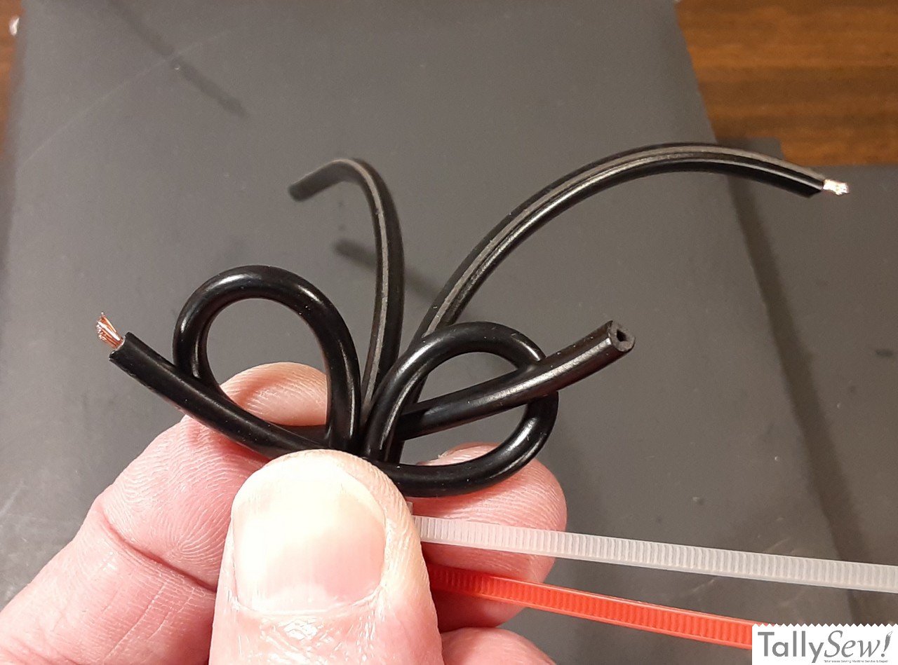
- Holding the two chords together take the front wire from the right hand cord and loop it clockwise in front of all of the wires.
- Take the front wire from the left hand cord and loop it down counterclockwise behind the two front wires and run the end through the loop created by the front right wire.
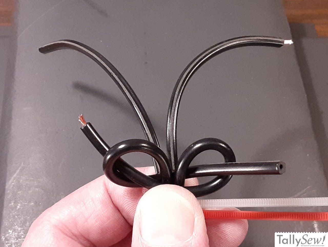
- Run the end of the first wire through the loop created by the second wire
- Pull the two wires so they create a tight knot up against the zip tie.
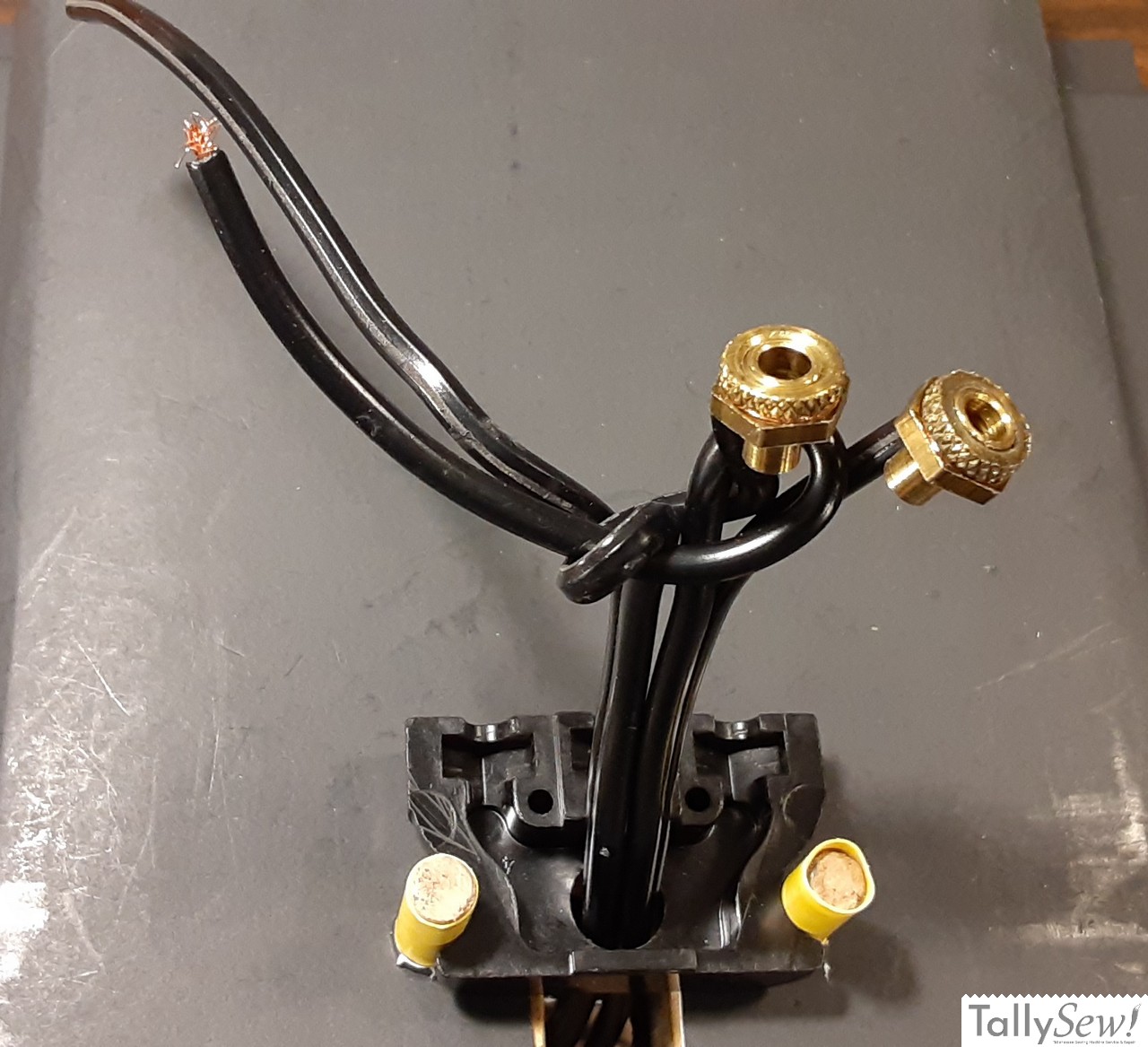
Insert the free end of the chords through the hole in the socket body and feed the cords through till the underwriters knot is touching the socket. Double check to make sure that your underwriter’s not is still secure and snuggly tied together
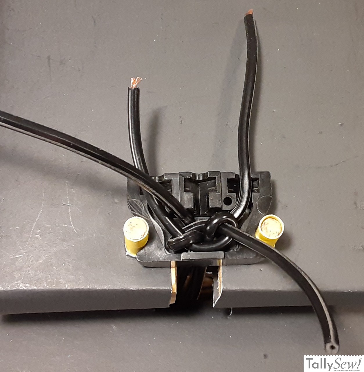
You can remove the zip ties now and pull the underwriters knot down into the open space inside the socket. Take some time to get a feel for how the wires are going to be routed to the terminals.
Please note that even though the polarity of each of these wires does not matter, what cord each wire belongs to DOES. Make sure you have the correct wire going to the correct terminal. Please refer to the included wire diagram at the top of the post.
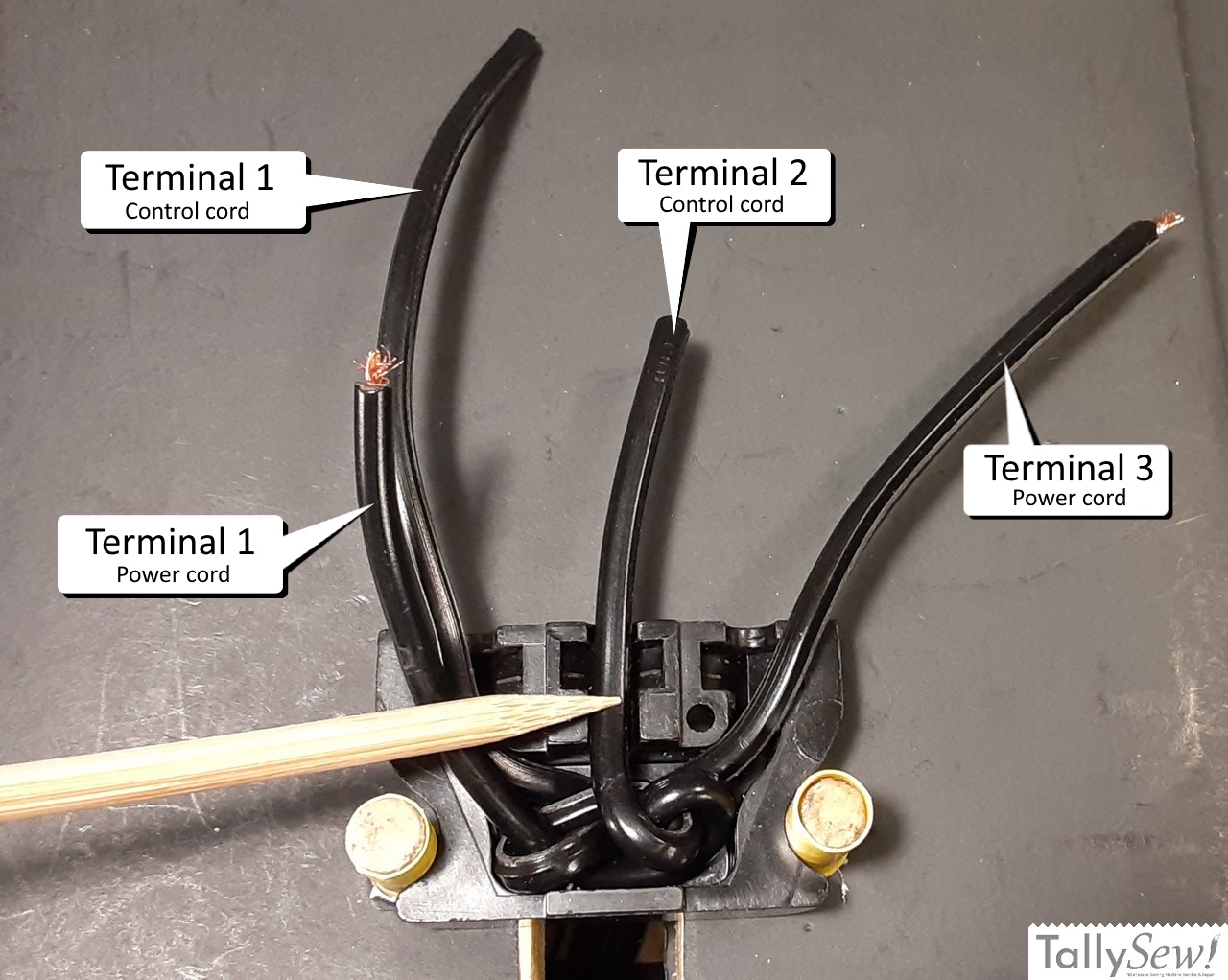
The two wires from the power cord are marked by the 1/8 inch of wire sticking out where you removed the insulation earlier. The power wires go on opposite sides of the plug, or terminals 1 and 3. Please refer to the included wire diagram.
The other cord is for the motor control and it’s wires will go to the left and center terminals, or terminals 1 and 2. Please refer to the included wire diagram.
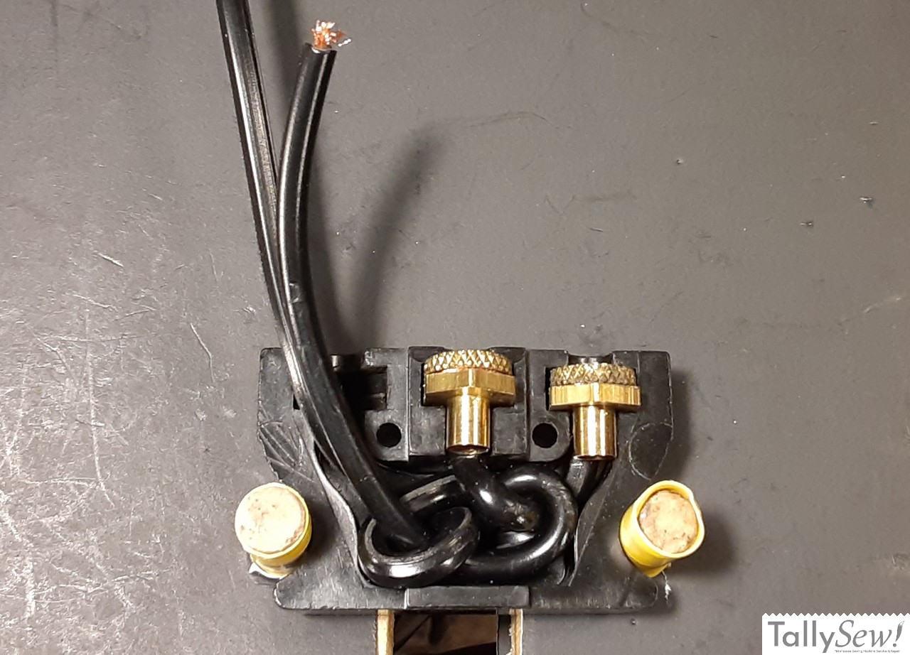
I like to go so far as to lay the wires out the way they will be routed to make sure the top and bottom of the plug fit together with the wires in place. It doesn’t have to be a perfect fit at this point, it’s just a way to see how well things go together, but does not indicate if you’ve got the wires in their correct locations.
Wiring terminal number two
Note: I’ve wired the terminals out of order because doing so makes getting the wires into position easier. There’s no requirement that you follow the pattern laid out in this tutorial, but if it’s the first time you’ve wired one of these plugs, and you’re using this tutorial, I’d recommend doing it the way I’m showing you… at least for your first time through.
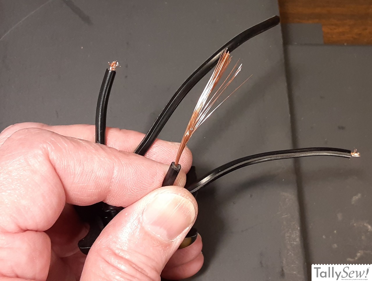
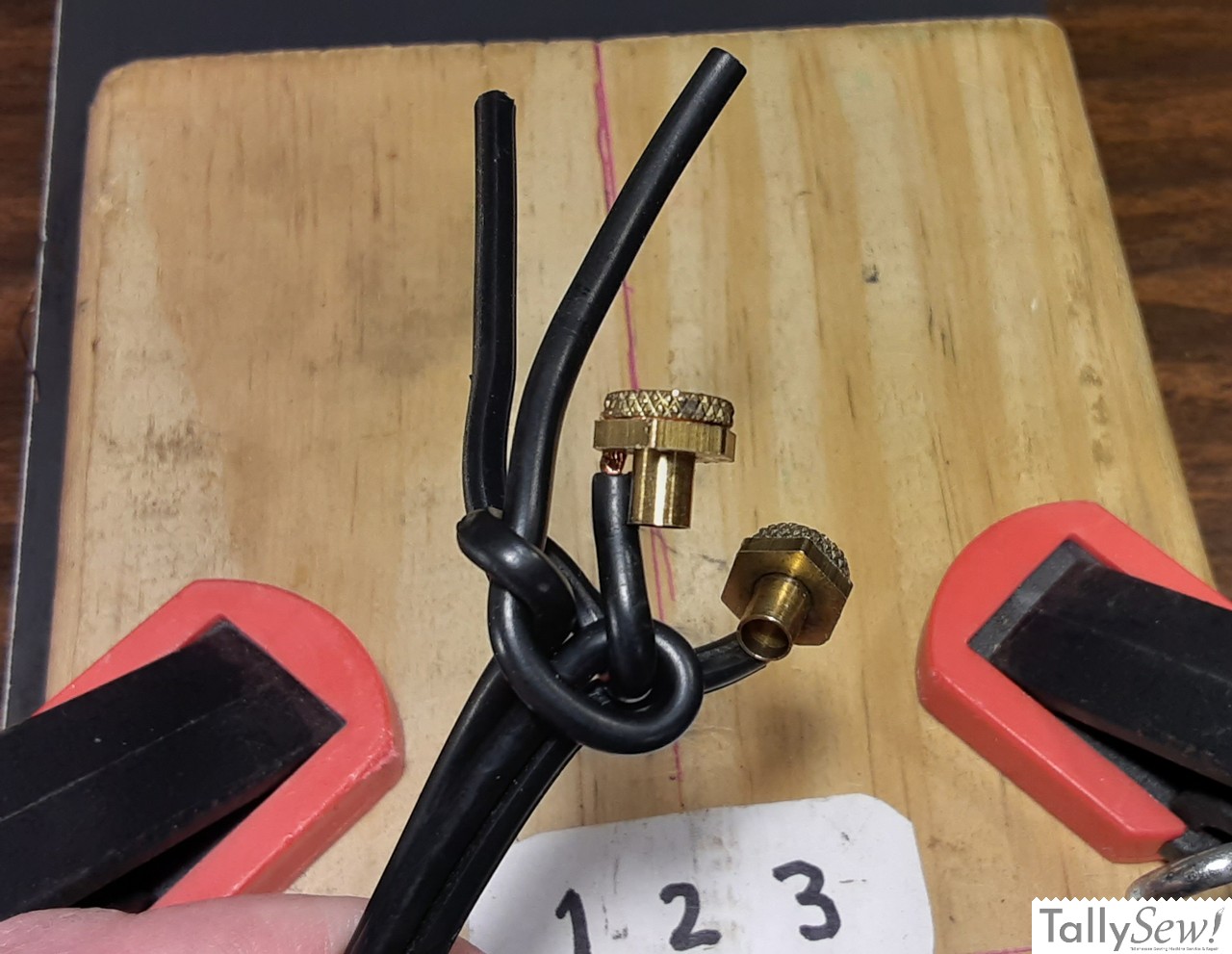
You should find that when you’re looking at the wires and the underwriters knot, you have a pair of wires on the left and a pair of wires on the right. You should also notice the pair on the left should have one wire missing ⅛ inch of insulation and one not missing insulation, and in the pair of wires on the right there should be one wire missing 1/8 of insulation and one not missing any insulation.
The motor control wire on the right (not missing insulation), will be connected to terminal number two. Route the power wire on the right hand side into the groove for terminal number three, then fold the motor control wire on the right hand side down so that it lays into the groove for terminal number two.

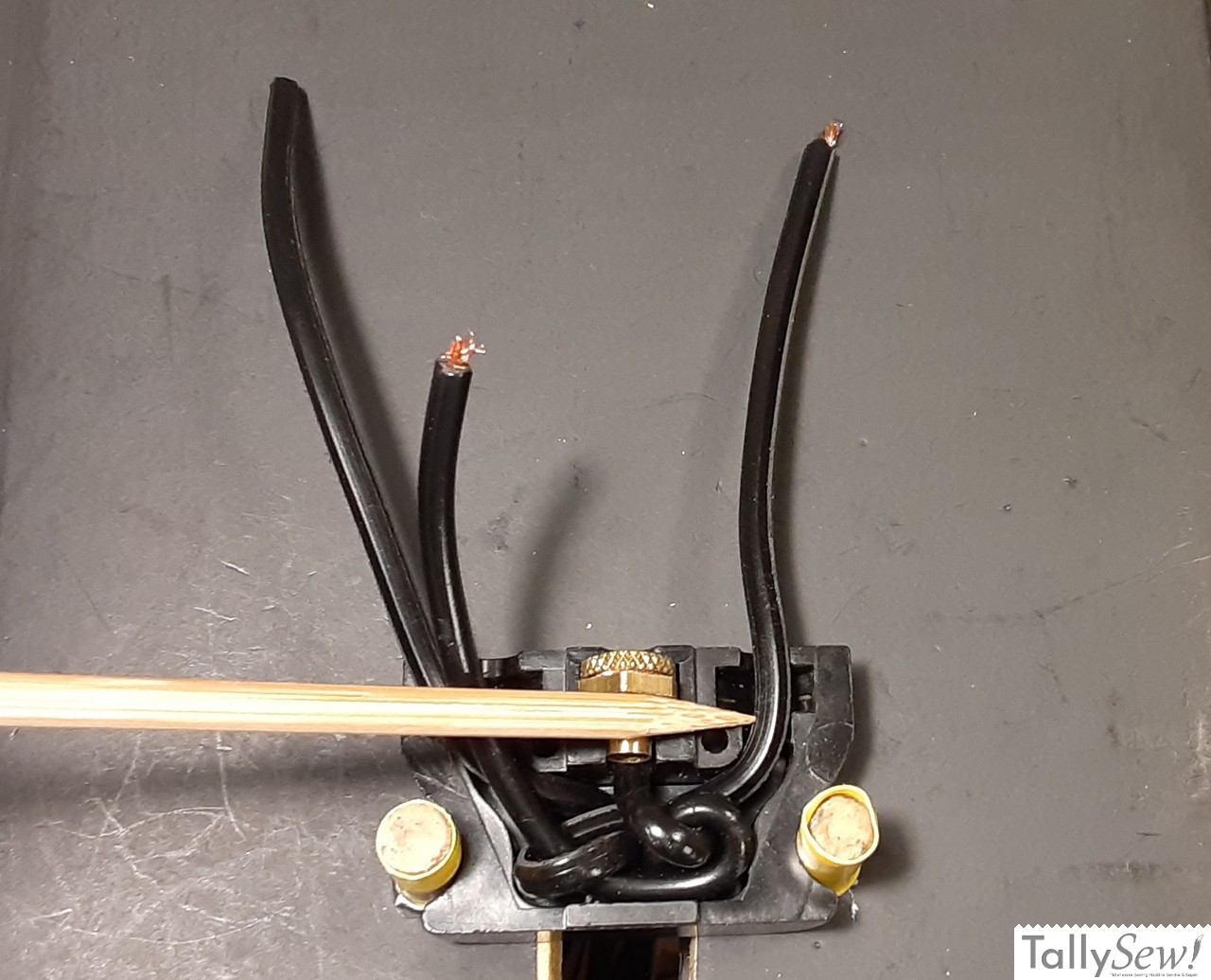
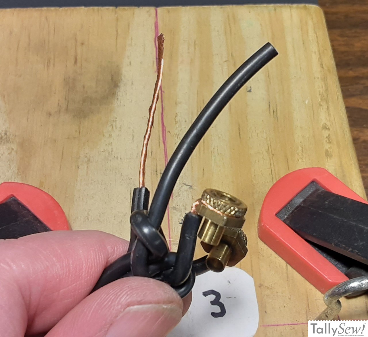
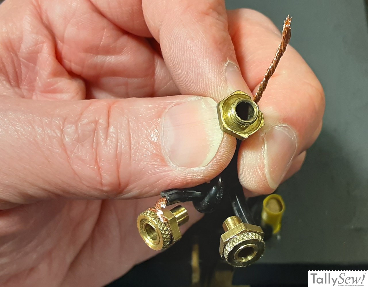
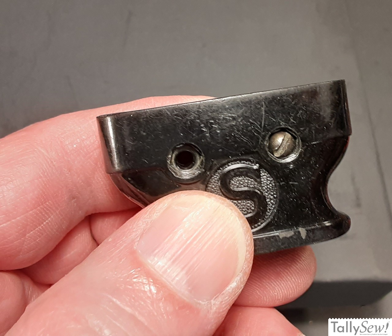
Using the blade of a screwdriver or your fingernail, mark the insulation on the motor control wire leading to terminal number two, right at the point where the hexagonal portion of the terminal begins, as indicated by the pointer in the photo above.
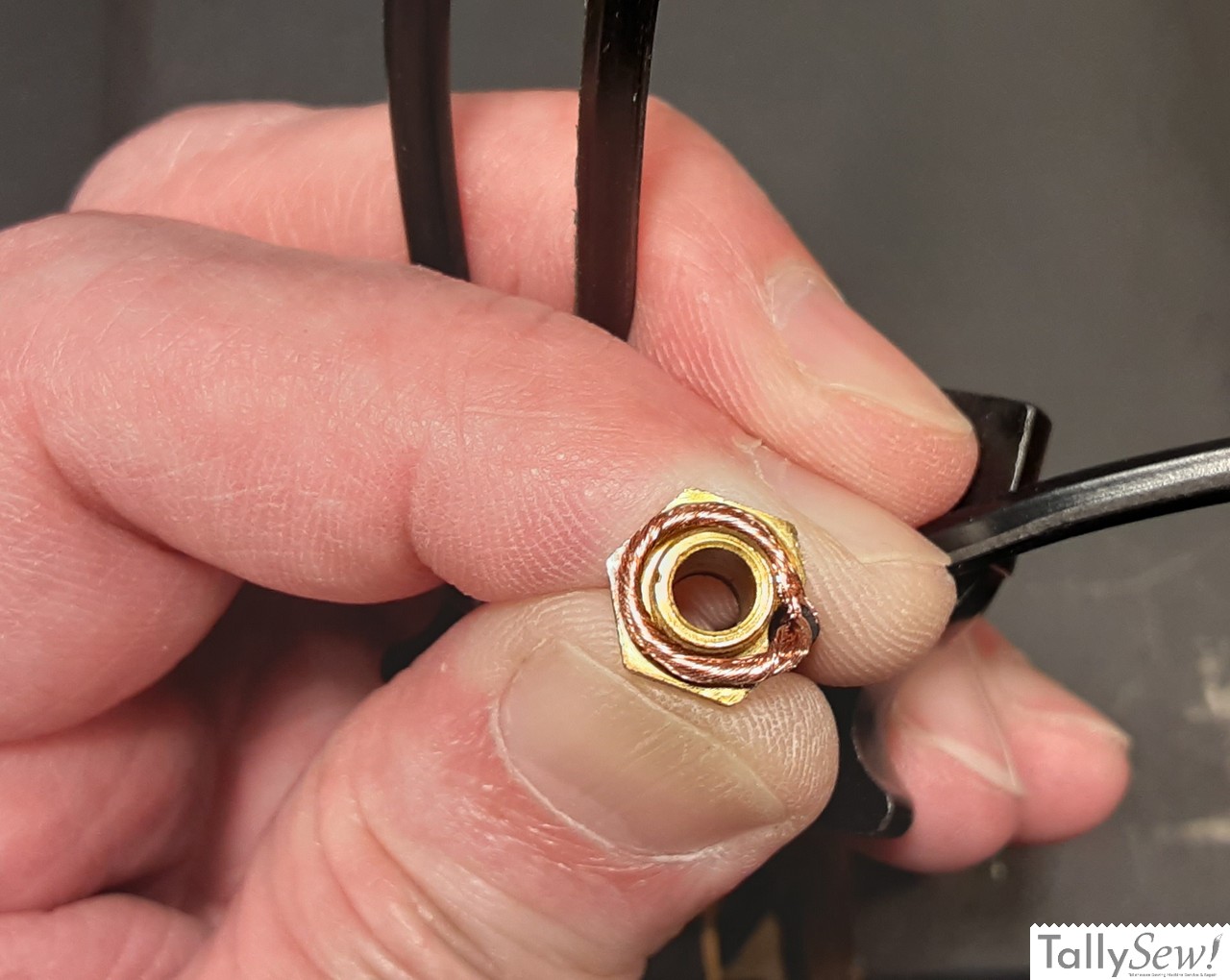
- Strip the insulation off of the wire that will be connected to terminal 2 so that the wire starts to be exposed just before the hex portion of the terminal will be when the terminal is in place.
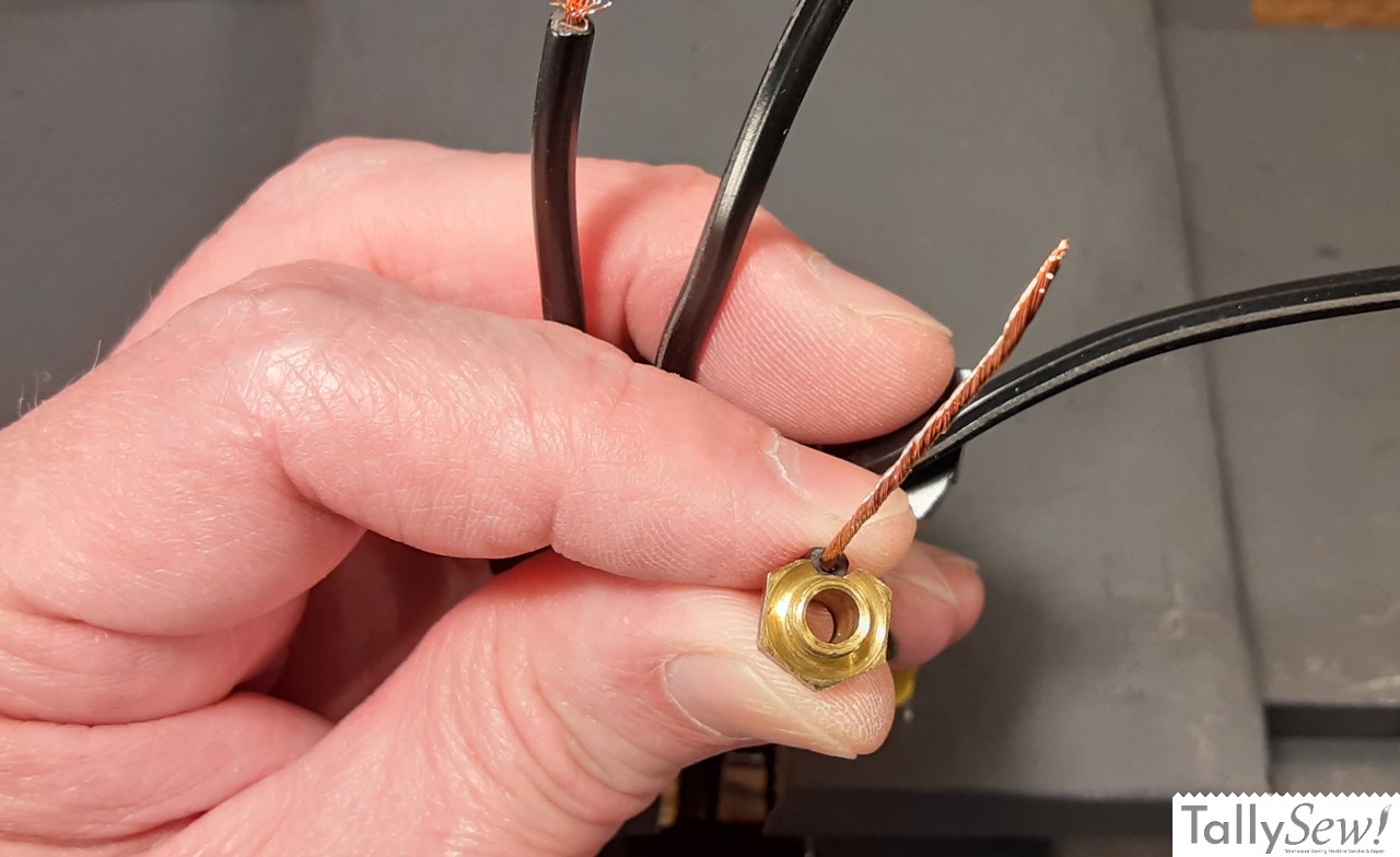
- Pull the cord up so you have some slack, and hold the insulated portion of the wire so that the stripped portion is sticking out. If the ring nut is still on the terminal, remove it. Place the terminal so that the bare wire fits in the slot in the hex portion of the terminal. The threaded end of the terminal should be pointed out, and the back of the hex should be against the end of the wire’s insulation. Gently twist the wire so that it will be easy to work with, but you aren’t trying to twist it to the point that it becomes overly stiff.
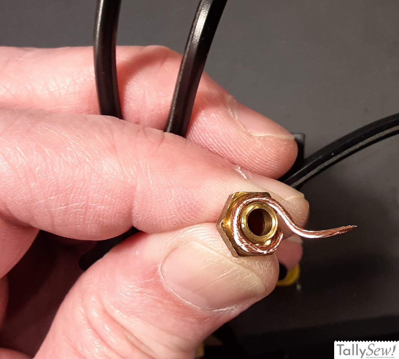
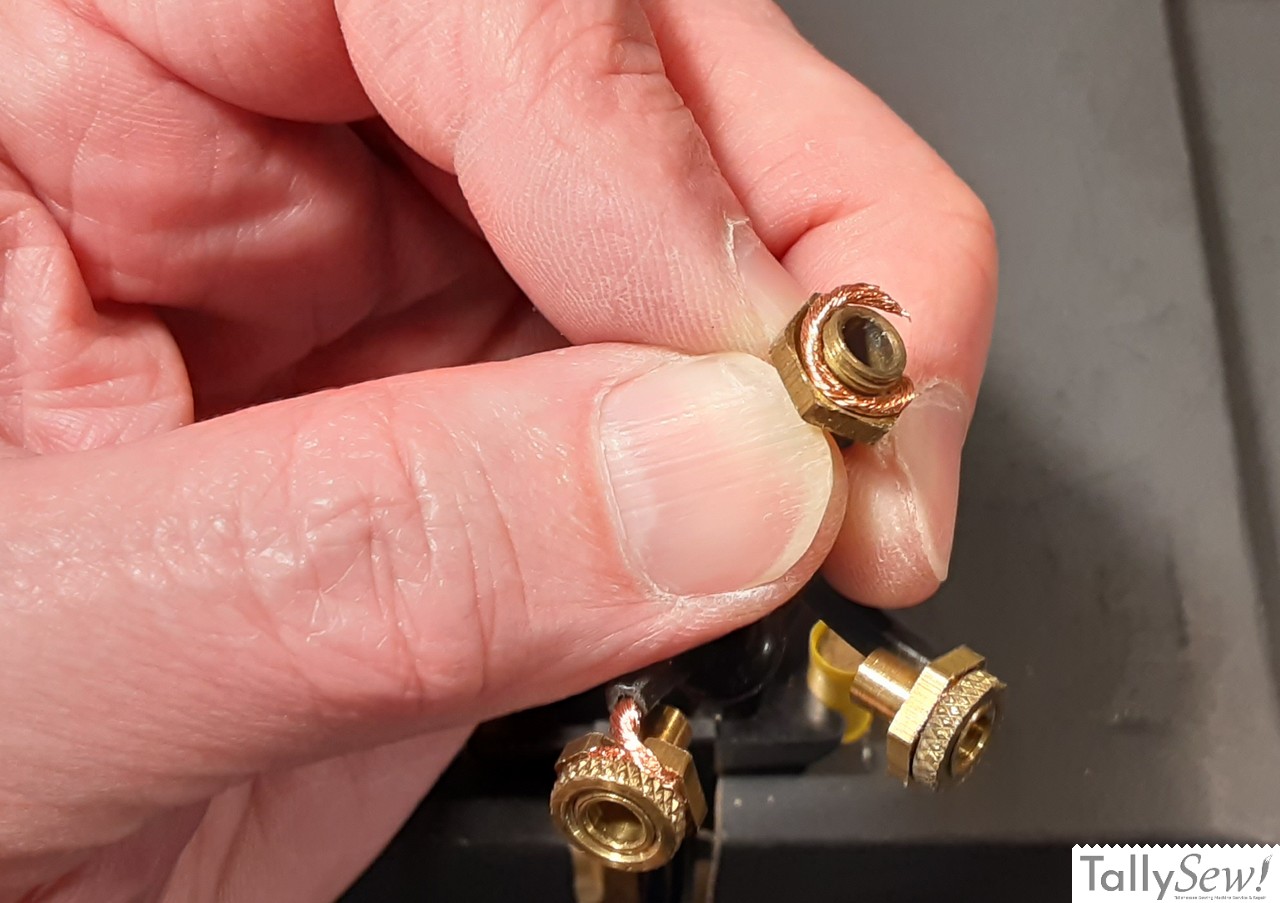
- Pull the exposed wire clockwise around the terminal close to the hex. If the twist of the wire has come loose you can twist it until it stays together.
- Clip off the extra wire just short of overlapping.
- Making sure the exposed wire is neatly in place against the terminal, screw on the ring nut making sure the concave face is towards the wire. The ring nut should be tight enough that you can’t unscrew it by hand.
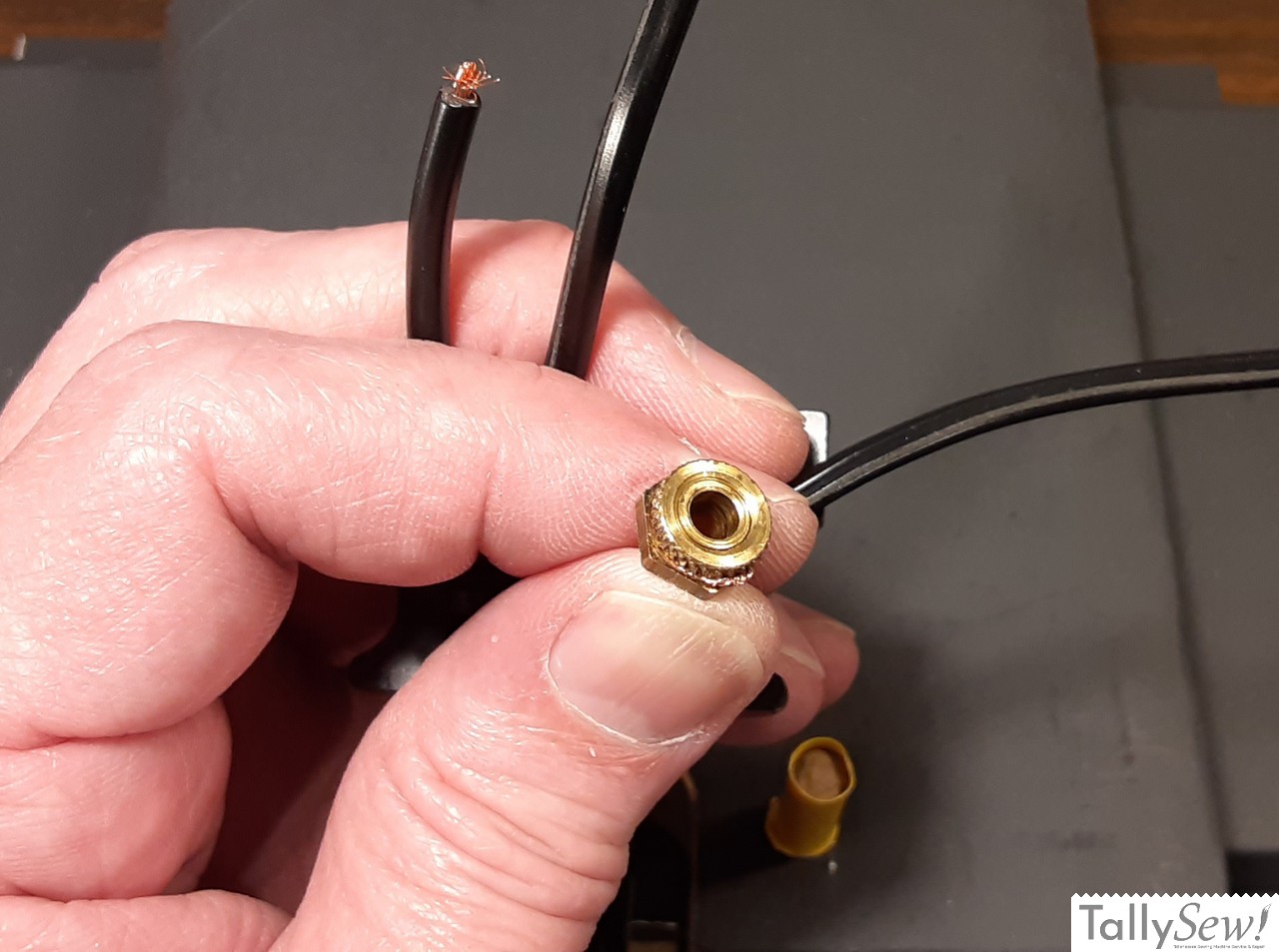
- Nest the wires back into the socket and put the now assembled terminal 2 in place. This placement is temporary, but needed to make sure the next terminal we work on will fit correctly.
Wiring terminal number three
Terminal 3 will be connected to the power cord wire on the righthand side. This should have 1/8 inch of wire stitching out since we used that to mark the two wires that make up the power cord.
Mark the insulation on the power cord wire leading to terminal number three, right at the point where the hexagonal portion of the terminal begins, as indicated by the pointer in the photo above.

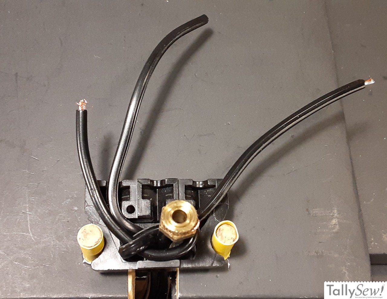
Assemble this terminal (terminal 3) the same way you assembled terminal 2, and then place terminals 2 and 3 in position in the socket.
Wiring terminal number one
As you discovered when looking at the wiring diagram, terminal one has two wires connected to it. These will be the two remaining wires, and consist of one power cord wire, and one control cord wire.
These two wires will need to be soldered together in a very specific way.
Note: Joining the two wires for terminal one can be done in several different ways, but in my opinion soldering provides a durable, low resistance connection, without taking up more space than necessary.

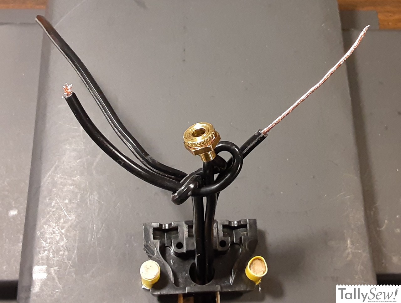
Mark the insulation on the power cord wire, and control cord wire leading to terminal number one, right at the point where the long end of the terminal begins*, as indicated by the pointer in the photo above.
* Notice that the area where insulation will be removed is different from how it was done on the other two terminals. More space is needed to allow room for the wires to be soldered together.

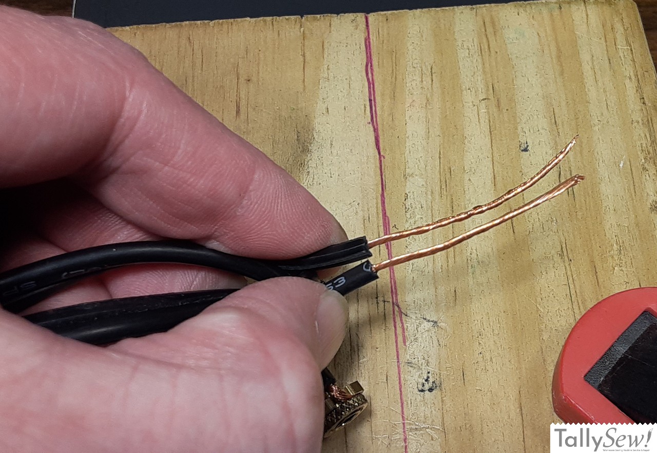

- Strip these two wires like you did for terminals two and three.
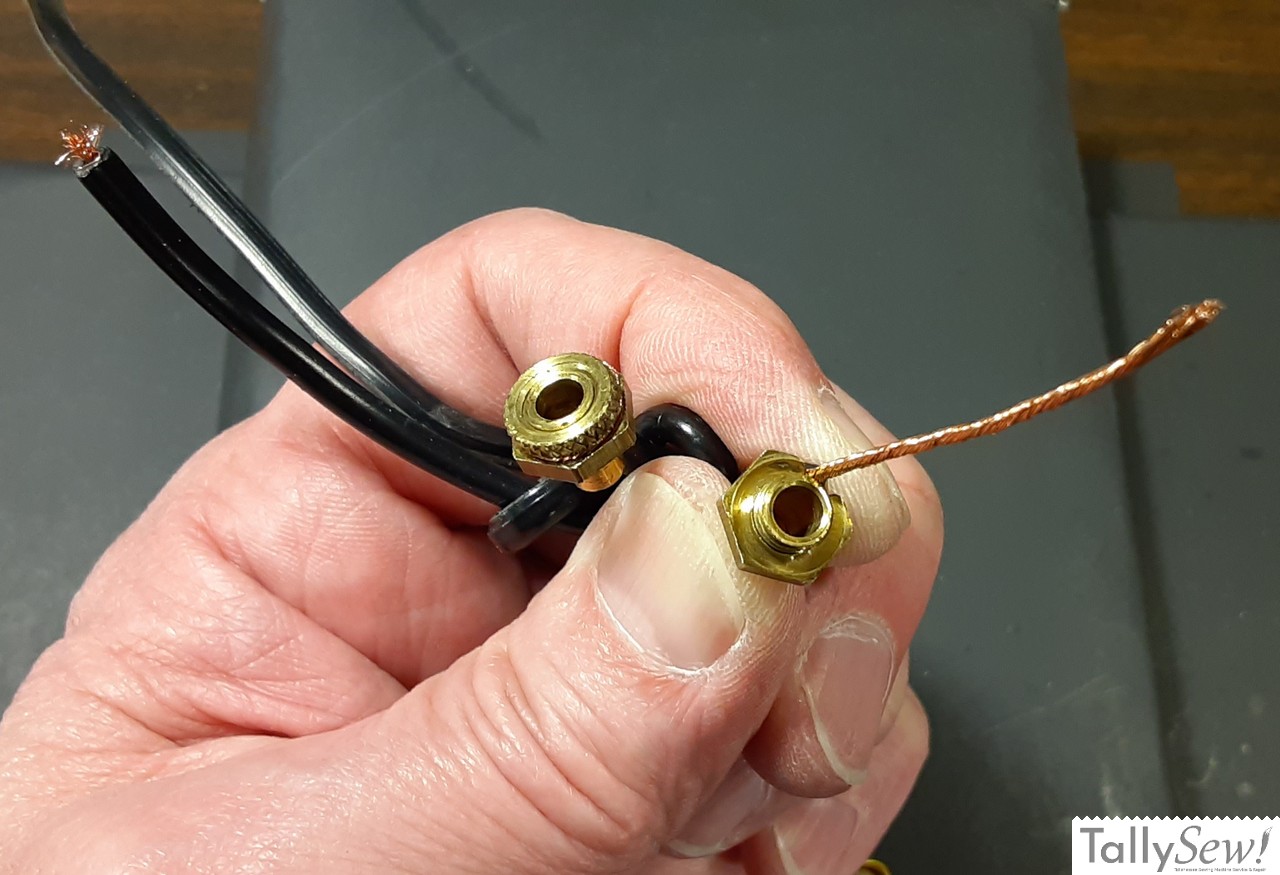
- Once both wires are stripped hold the two wires side by side.
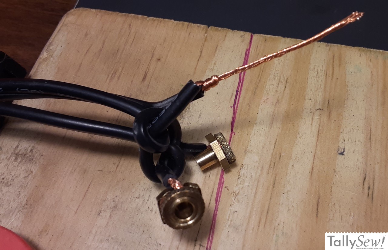
- Wrap one of the wires around the other three times keeping the wrap as close to the base of the connection as possible without overlapping the wrapped wire.
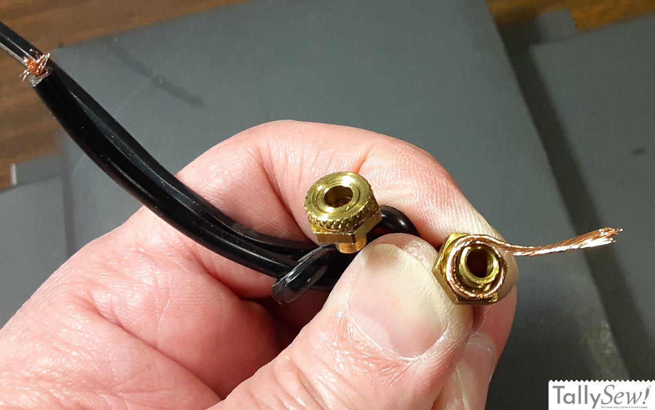
- Trim the excess wire sticking out after wrapping.
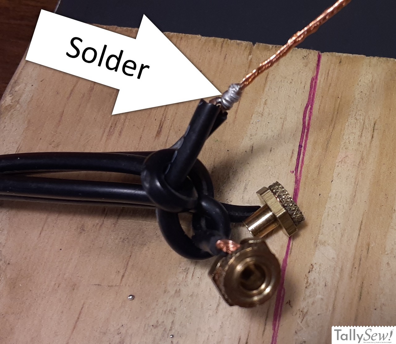
- Solder this connection, keeping the solder confined to the wrapped area.
- If you find later that the solder has wicked up the wire far enough that it would be clamped by the ring nut you will need to start over. To reiterate, DO NOT solder the area that connects the wire to the terminal.
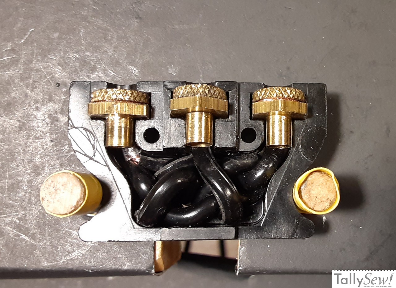
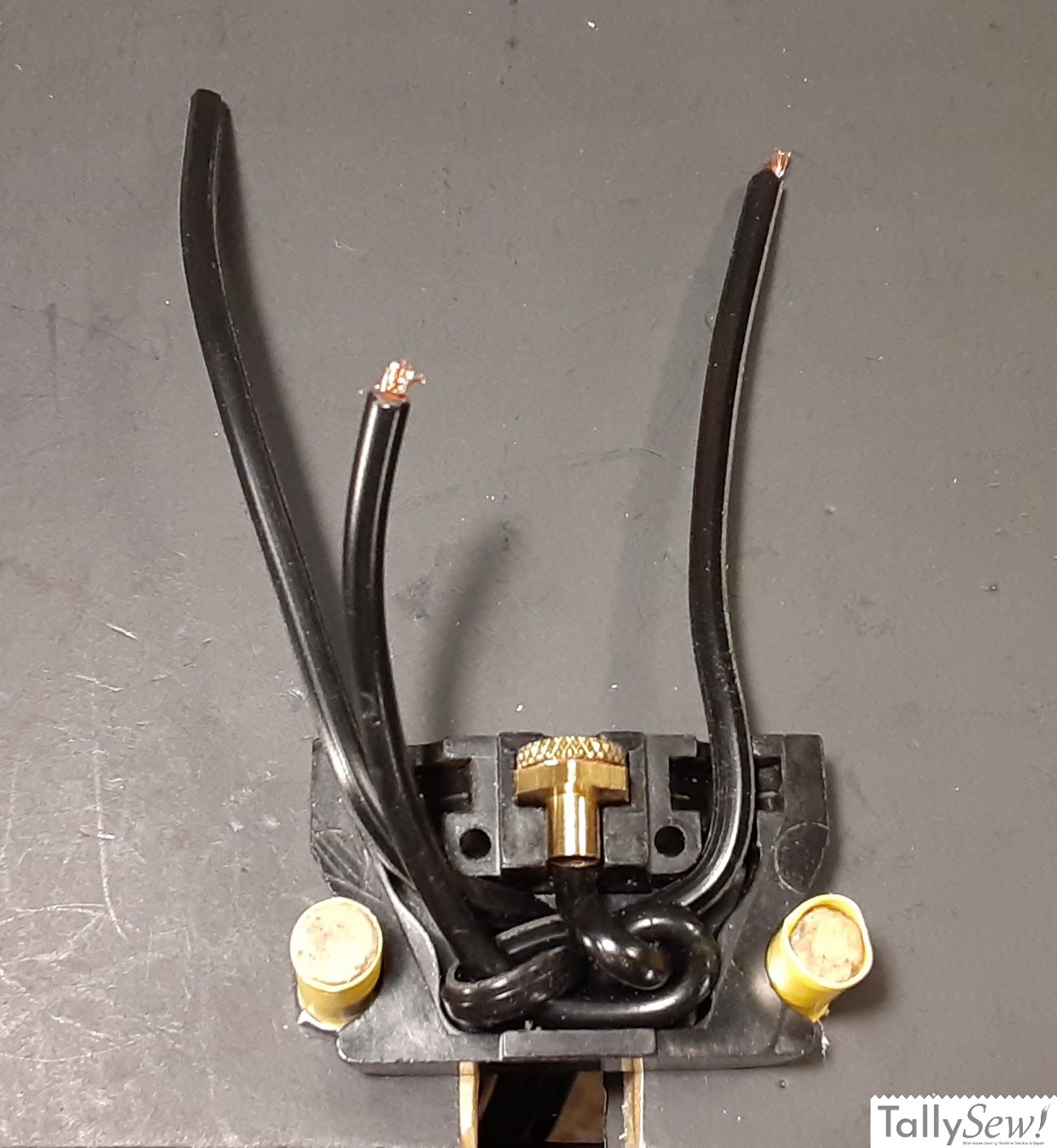
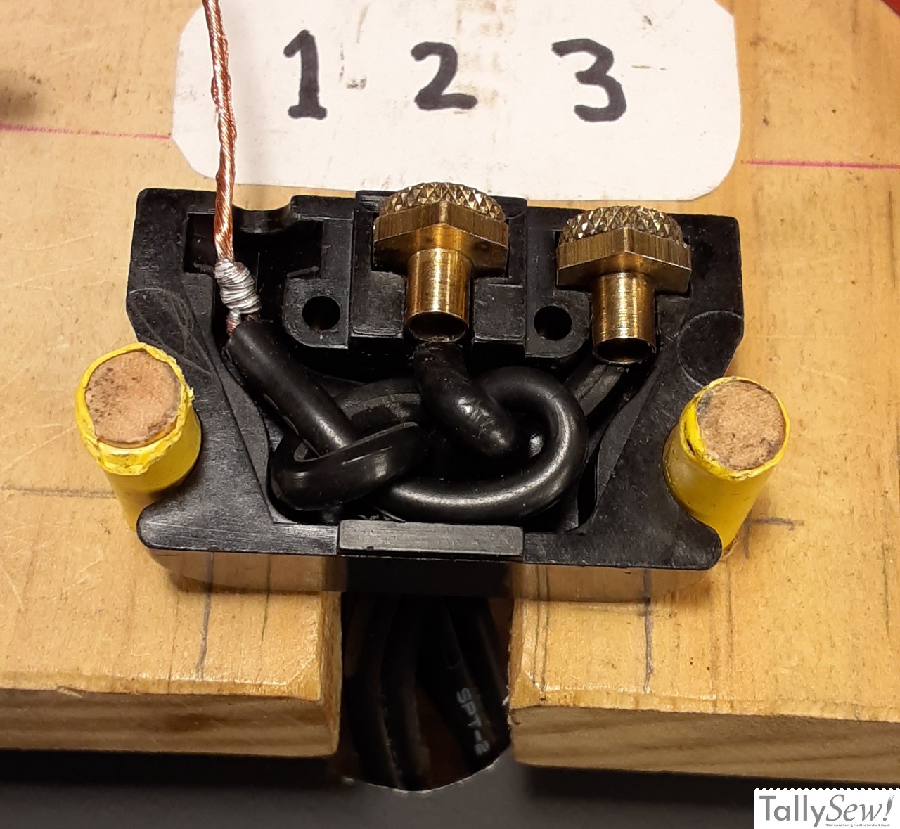
Assemble terminal one the same way you assembled terminals 2 and 3, while keeping the base of the hexagonal part of the terminal backed against the wrapped and soldered part of the wire. After terminal one is assembled fit all three terminals into their places and make sure the wire and underwriters knot are tucked into the area supplied for them.
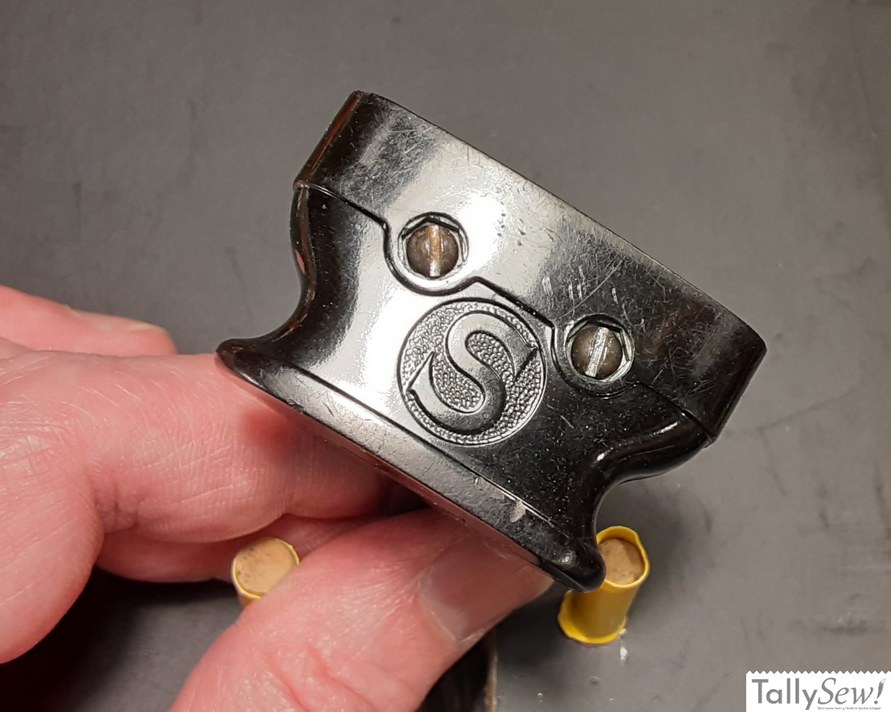
Some of these sockets have hex shaped pockets on only on the top of the plug, others on the top and the bottom. One way or the other, the hex nuts fit in those pockets, and the screw can fit in a hex pocket or round pocket. Make these screws snug but DO NOT OVERTIGHTEN! Bakelite is very hard and kind of brittle.
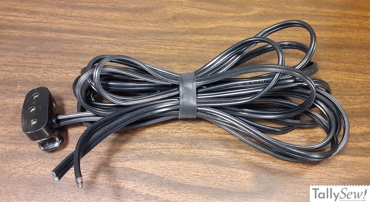
Plug with power and control cords ready for a wall plug and motor control, but that’s a story for another day.